
TM 5-3895-385-23-2
0326
Rocker Lever Assembly Adjustment -- Continued.
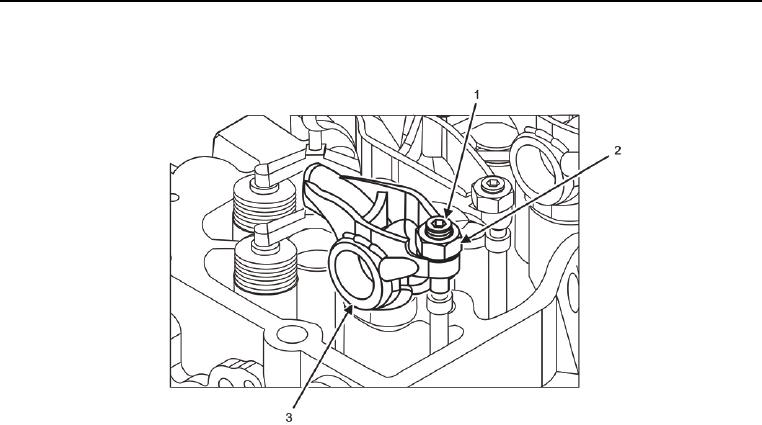
Figure 6. Valve Clearance Measurement.
NOTE
The following steps provide information to adjust the intake valve of cylinder 1. Procedures to
adjust the other valves with engine set at TDC in Table 1 are the same. Different thickness gages
are required for intake and exhaust valves as indicated in Table 1.
8. Loosen lock nut (Figure 6, Item 2) on adjustment screw (Figure 6, Item 1) of cylinder 1 intake valve.
9. Adjust clearance between crosshead and rocker arm (Figure 6, Item 3) by turning adjustment screw (Figure 6,
Item 1).
10. Hold adjustment screw (Figure 6, Item 1) in position and tighten adjustment screw lock nut (Figure 6, Item 2).
11. Insert appropriate size thickness gage from Table 1 again between crosshead and rocker arm (Figure 6, Item
3) of cylinder 1 intake valve to ensure adjustment was not changed when lock nut (Figure 6, Item 2) was
tightened.
12. Repeat steps 10 through 12 to measure valve clearance of cylinder 3 exhaust valve. Adjust as necessary to
meet clearance specification in Table 1.
13. Repeat steps 10 through 12 using appropriate size thickness gage from Table 1 to measure valve clearance
of cylinder 1 and cylinder 2 intake valves. Adjust as necessary to meet clearance specification in Table 1.
14. Rotate crankshaft pulley 360 degrees clockwise beyond TDC.
15. Repeat steps 10 through 12 using appropriate size thickness gage from Table 1 to measure valve clearance
of cylinder 2 and 4 exhaust valves. Adjust as necessary to meet clearance specification in Table 1.
16. Repeat steps 10 through 12 using appropriate size thickness gage from Table 1 to measure valve clearance
of cylinder 3 and 4 intake valves. Adjust as necessary to meet clearance specification in Table 1.
17. Remove barring tool and install plug.