
TM 5-3895-385-23-2
0326
Rocker Lever Assembly Adjustment -- Continued.
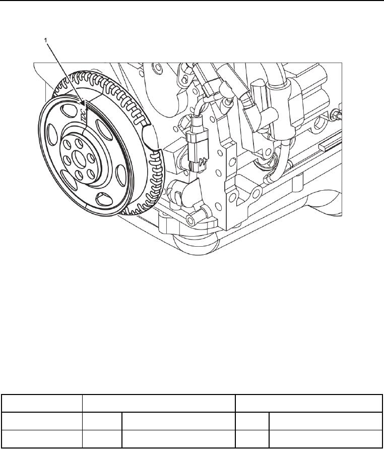
Figure 5. Crankshaft Timing Mark and Pointer.
4. Set TDC mark (Figure 5, Item 1) at 12 o clock position.
5. Verify both cylinder 1 rocker arms (Figure 6, Items 1 and 2) are loose.
6. Rotate crankshaft 360 degrees clockwise if cylinder 1 rocker arms (Figure 6, Items 1 and 2) are not loose.
7. Verify both cylinder 1 rocker arms (Figure 6, Items 1 and 2) are loose after crankshaft rotation.
NOTE
The procedure to adjust valve clearance is the same for all valves, but the valve clearance
specifications for intake valves are different from the specifications for exhaust valves.
Table 1. Valve Clearances.
Crankshaft
Adjustment Intake Valve
Adjustment Exhaust Valve Clearance
Position
Clearance
Cylinders 0.006 in (0.152 mm) min
0.015 in (0.381 mm) min
TDC
1, 3
1, 2
0.015 in (0.381 mm) max
0.030 in (0.762 mm) max
0.006 in (0.152 mm) min
0.015 in (0.381 mm) min
TDC + 360 degrees
3, 4
2, 4
0.015 in (0.381 mm) max
0.030 in (0.762 mm) max