
TM 5-3895-385-23-2
0326
Rocker Lever Assembly Adjustment
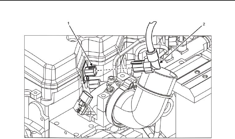
Figure 4. Injector Harness Pass-Through Connectors.
CAUTION
Allow engine to cool before measuring valve clearance. Engine coolant must be less than 140F
(60C) before valve clearance can be measured. Failure to comply may cause damage to
equipment.
1. Disconnect fuel injector wire harness W25 C3 and C4 (Figure 4, Item 2) at pass-through connector (Figure 4,
Item 1).
2. Remove plug under starter and install barring tool.
NOTE
Engine TDC is indicated by markings on the crankshaft pulley at the front of the engine. TDC has
been established when the crankshaft has been rotated to a position where both cylinder 1 rocker
arms are loose.
3. Turn barring tool clockwise using a breaker bar to establish Top Dead Center (TDC).