TM 5-3895-373-20
4.11.
REPLACE INDUCTION HEATER RELAY - Continued.
A. REMOVE Continued.
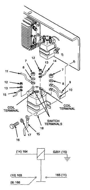
2. REMOVE RELAY WIRES.
a.
Remove hex nuts (7) and flat washers (8) from
both relay switch terminals.
b.
Remove wire 166 (9) and wire 103 (10) from
relay switch terminal. Remove wire 165 ( 1) from
opposite relay switch terminal.
c.
Remove hex nuts (12) and flat washers (13)
from both relay coil terminals.
d.
Remove wire 164 (14) and ground wire G201
(15) from relay coil terminals.
3. REMOVE RELAY FROM PANEL.
a.
Remove hex head cap screws (16), flat washers
(17), and ground wire G201 (15) from relay (18).
b.
Remove relay (18) from panel.
B.
INSTALL.
1.
INSTALL RELAY ON PANEL.
Thread locking compound solvent
can cause eye damage. Wear safety
goggles/glasses when using. Avoid
contact with eyes. If solvent contacts
eyes,
flush
with
water
and
get
immediate medical attention.
a.
Clean hex head cap screws (16) with thread
locking compound solvent.
b.
Install flat washers (17) and ground wire G201
(15) onto hex head cap screw (16).
GO TO NEXT PAGE
4-66