
TM 5-3895-356-14&P
If the roller bearing (50) is removed from the cover, then
EXCEPTION
the inner race must also be replaced, as they are a
matched set.
On older units, nuts and lock washers are removed from
studs. Do not remove studs from housing unless
NOTE:
damage is evident.
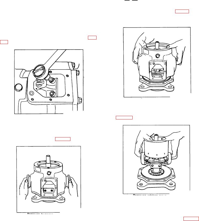
10. Remove housing (8) as shown in Fig. 14 by lifting
Control assembly must be removed
housing straight up until all internal parts are cleared. Do
from pump at this point to proceed to
not disturb internal parts during this operation.
Step 7.
7. Using an Allen wrench, remove Allen socket head
cap screws (28) from the cam control lever assembly
(35). Remove lever assembly from cam (12). See Fig.
Figure 117.
Removing housing
11. Lift off rotating group consisting of parts (12, 18,
19, 20, 34, 37, 51, 52, 53, 54, ) from mounting flange (2).
See Fig. 118.
Figure 115.
Removing cam lever arm
8. From the sides of the housing (8) remove hex bolts
(5) and lock washers (6). Pull out trunnions (7) and
thrust washers (27) as shown in Fig. 116.
Figure 118.
Removing rotating group
12. At the factory each block is marked to indicate
cylinder bore number one., Mark piston number one with
felt pen or a similar devise as a convenient method of
Figure 116.
preserving the bore/piston relationship. See Fig. 119.
Removing trunnions
Remove cylinder block (37) by lifting straight up until
9. Remove hex bolts (3) and lock washers (4) from
piston assemblies are cleared.
using (8).
92