
TM 5-3895-356-14&P
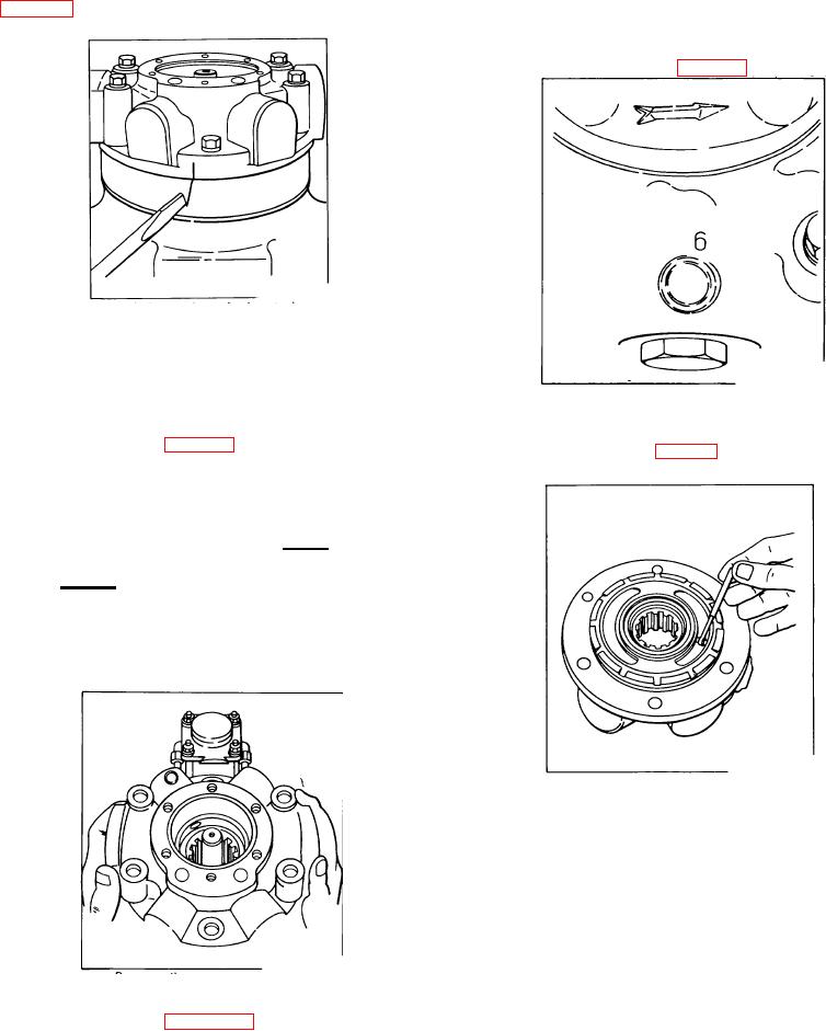
5. Mark the housing (8) and cover (9) to insure proper
NOTE:
orientation upon reassembly. A scratch in the paint
Pump displacement can be confirmed
across the housing/cover parting line may be used. See
by one of the two methods described
below:
a. In the area of the trade mark, cast in the cover, will
be stamped a "6" or a "4" denoting a Model 60 or a
Model 45 respectively. See Fig. 113
Figure 111.
Marking across the cover/housing parting line
Remove hex bolts (40 & 22) (2 short, 4 long) and lock
washers (4). Lift off the pump cover (9). If the cover
Figure 113.
should stick to the housing, jar loose with a soft faced
Displacement identification stamp
hammer. Remove O-ring (38) and cover gasket (39)
b. Measure the width of the cover kidney, near the mid
from pump cover. See Fig. 112.
point, as illustrated. See Fig.114.
CAUTION
It is important that every precaution
be taken to protect the bronze face
on the cover from damage. Never lay
the cover down on the bronze face.
Do not allow miscellaneous parts or
tools to come in contact with the
bronze face.
A nick or scratch
resulting
from
a
moments'
carelessness can easily damage a
cover beyond repair.
Figure 114.
Measuring kidney width
If the width is .34 Inches approximately, the pump is a
Model 45.
If the width is .40 inches approximately, the pump is a
Model 60.
6. Inspect the cover roller bearing (50) for galling of the
rollers, roughness, or fracture of the cage. If any of
these conditions exist, press the roller bearing (50) from
Figure 112.
the pump cover (9).
Removing the pump cover
91