
TM 5-3895-356-14&P
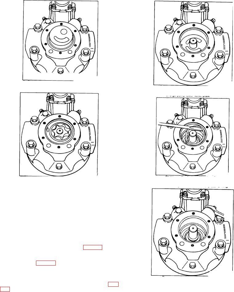
Figure 106.
Figure 108.
Charge pump upper valve plate.
Charge pump lower valve plate.
Figure 107.
Figure 109.
Charge pump eccentric, inner and outer
Removing the lower valve plate O-ring.
gerotor
2. Remove charge pump spacer assembly (48), which
includes the spacer and a dowel pin. Do not remove the
dowel pin from the spacer assembly unless damaged.
Note the relationship of the lower valve plate (42),
upper valve plate (45), and spacer assembly (48)
which is determined by the alignment of the dowel pin
with the recessed hole in the inner face of the charge
pump cover (10). This relationship must be preserved
upon reassembly to insure the proper function of the
charge pump. Remove charge pump assembly (47)
consisting of inner and outer rotor. See Fig. 108.
3. Remove pin (46) from shaft (1). Lift out lower charge
pump valve plate (42) and, using a screw driver, remove
O ring (41). See Fig. 109.
4. Remove control sense lines (8) (if applicable) from
tube fittings (9). Remove check valve assemblies
consisting of check valve plugs (61), O-rings
Figure 110
(62), valve springs (60) and plungers (59). See Fig.
Removing the control sense lines
90