
(in comparison to properly tightened frames) to deform the
spring hangers. If spring should be deformed, straighten or
replace before attaching new screed bottom. Loose or
deformed spring hangers can be a cause for poor screed
control.
(2) Install crown gauge pointers No. 3.
(3) Position new screed bottom so that studs align with
holes
in
the
screed
frame.
Then,
lower
screed unit onto Screed Bottom and fasten with
GRIPCO
Center
Lock
Corrosion
Resist
Nuts.
Before
tightening
GRIPCO
Nuts,
push
screed
bottom as far forward as possible. Then, tighten
Supporting Crowning Arms For
Screed Bottom fastening nuts to 90 Ft./lbs. torque.
Screed Bottom Removal
(4) Install strike-offs to screed bottom. Check to
Figure 32
make sure that strike-offs are not gouging or locking
against mold board. Also check for excessive
SCREED UNIT
clearance between strike-offs and mold board. If
clearance is excessive, tack weld a 1/4" rod of
Removing Quick-Change Screed Bottom (Refer to
required length to top of strike-offs. Failure to
Figure 33)
properly seal this area will allow asphalt to seep into
1) Adjust screed crown to "O" crown. Then
screed bottom making the change in the screed
place wood blocks as shown in Figure 32, Item "Z"
bottom more time-consuming.
to support crowning mechanism. These blocks must
(5) Install walkway.
extend under both front and rear crowning arms
and on both right and left hand side of screed. This
CAUTION: If screed bottom is to be reversed the
will hold frame level and allow studs to align with
inside of screed must be thoroughly clean, to insure
support frame bolts.
proper seating of frame to screed bottom, and
(2) Remove walk-way
consequently obtain the maximum tightness with
(3) Remove Strike-off bolts No. 1 and No. 5.
fastening studs and nuts.
(4) Remove Screed bottom GRIPCO Nuts No.
2. (5/8" GRIPCO Corrosion Resist - Center Lock).
(5) Remove crown guage pointers No. 3
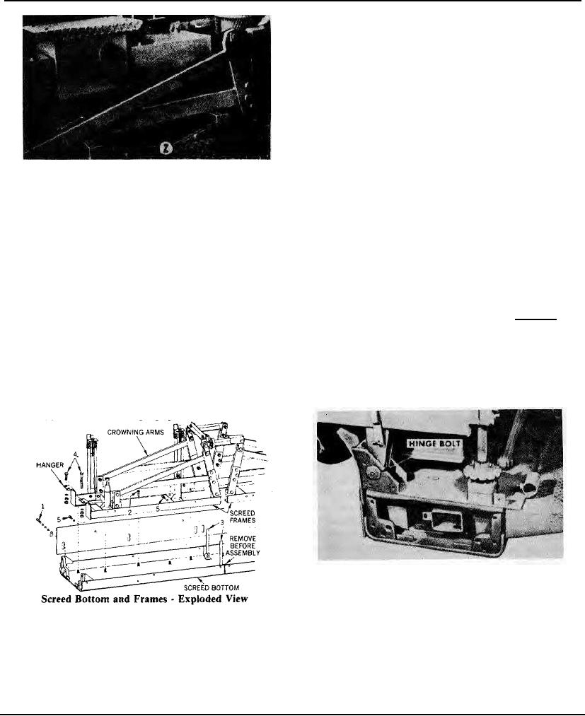
Location Of Screed Hinge Bolt
Figure 34
SCREED BOLTS
Screed Bottom and Frames-Exploded View
The bolts which attach the screed bottom to the
Figure 33
frame and the frame tc the pull arms must be kept
tight at all times. When bolts become loose and the
Install Screed Bottom as follows:
screed bottom is no longer rigidly held, waves may
(1) Check tightness of bolts No. 4 that fasten frame
appear in the finished mat. Check all screed bolts
spring hangers to top frame. If screed frames are operated
frequently for tightness.
with loose fastening bolts, it will take only one-half the load
In the event that the hinge bolts (Figure 34)
Page 114