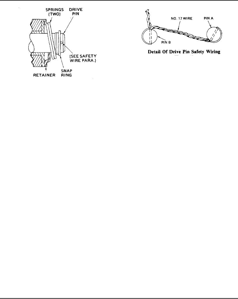
Detail Of Drive Pin Safety Wiring
Figure 43
DRIVE PIN SAFETY WIRING
Whenever the safety wire on brake drive pins (9) is
Detail Of Brake Auto-gap Drive Pin
removed, it should be restored before the brake is
Figure 42
again operated. See details in Figure 43.
(Refer to Figures 41 & 42 for Part Identification)
Brake Armature Clearance
The magnet ring (3) is bolted to the paver track
Automatic wear adjustment, or armature follow-
drive gear case, with the case input shaft extension
up, is provided by allowing the armature to slide
(16) passing through the ring but not attached to it.
freely axially on the drive pins. (See Figure 42). This
This ring contains the permanent magnets and the
provides maximum armature life with a minimum
windings of the electro magnet. Its outer face
amount of care and attention. As the friction
includes the friction surface (4). Armature (2) is the
surfaces "wear in" the armature advances on the
movable disc which is loosely held by four drive pins
pins so full contact with magnet is maintained at all
(9) and coil springs. These pins project from hub (7)
times.
which is keyed to the input shaft extension from the
gear case. The armature (2) is free to move laterally
Wear Pattern
along the shaft but is slaved to the shaft by the drive
Wear grooves appear on the armature and
pins. The permanent magnets therefore draw the
magnet surfaces after extended service, (Figure 41).
armature tight against the friction face (4) of the
This is a normal wear condition and will not impair
stationary magnet ring (3). This prevents any
functioning of the unit or cause it to lose torque. In
movement of the armature and consequently any
fact, a new brake may require burnishing, or
rotation of the gear case shaft.
running-in, before maximum rated torque may be
Small coil springs on the drive pins (9) are
developed. Never machine the armature or magnet
compressed when the armature is held by the
contact surfaces to remove grooving or scoring.
permanent magnets. When the brakes are to be
Remachining the face of a worn armature is never
released the operator moves the console toggle
recommended. But a worn magnet face should
switch to Neutral or Travel. Electric current then
always be machined if it is to be used with a
energizes the electro magnetic coil in the magnet
replacement armature. In refacing a worn magnet:
ring (3) and neutralizes the magnetic attraction of
(1) machine only enough material to clean up the
the permanent magnets. The coil springs on the
entire face of the magnet; (2) hold face within .005"
drive pins force the armature (2) away from the
of parallel with the mounting plate; and (3) undercut
frictioi face on the magnet ring and the armature
the molded facing material .002" to .004" below the
and gear case shaft are then free to rotate. When the
pole faces.
brake switch is at Neutral or Travel there must
always be a clearance between the armature and the
WHEN TO REPLACE WORN ARMATURE
magnet ring friction face.
AND ROTOR
As the friction faces wear from repeated
The brake armature-rotor set is completely worn
application of the brake, the gap between them
out when 9/32" of the combined friction faces has
increases. The desired gap of 1/16" should be
been worn away. When this occurs the two parts
maintained by adjustment of the armature hub (7)
must be replaced in order to avoid brake slippage at
and its taper-lock bushing (8) on shaft (16).
a critical time.
Page 118

