
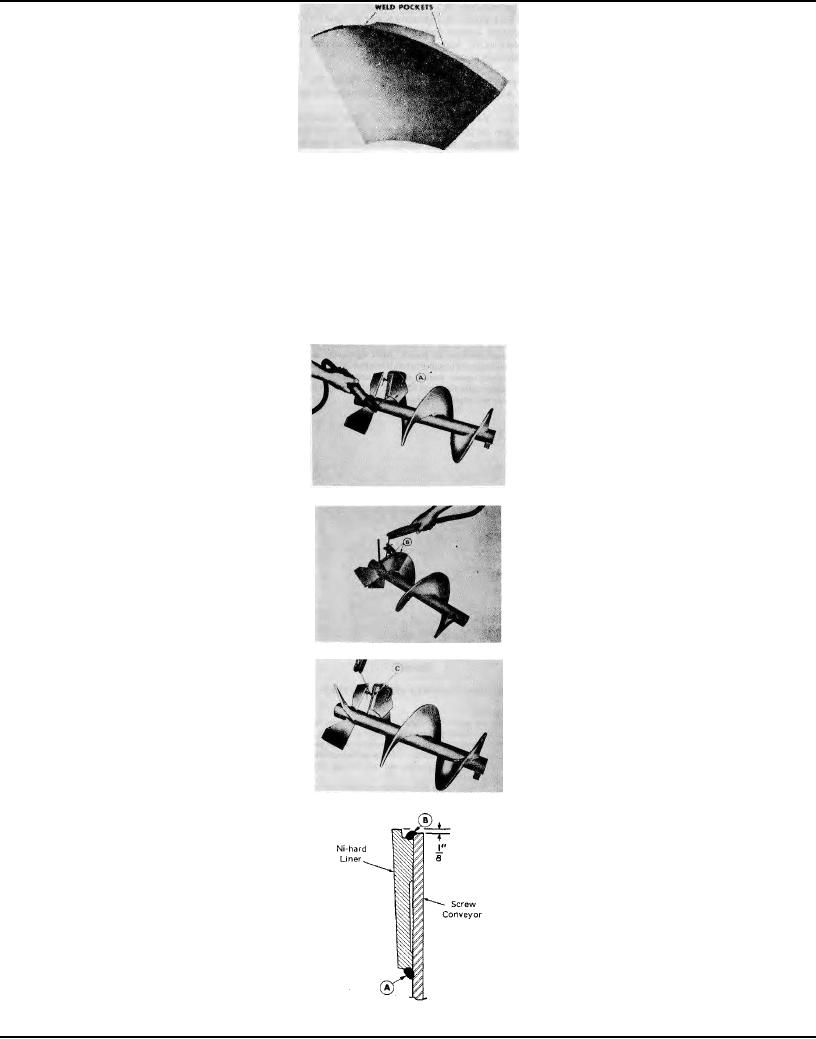
Formed Ni-hard Liner For Screw Conveyors Figure 23
(3) Using several C-clamps attach the pieces of liner to the screw face starting at the drive shaft end as shown in
Figure 24. By starting at this end, the main wear surface of the section will be covered and any small area not covered
will be at the discharge end. Adjust liner pieces to extend about 1/8" above the edges of the screw flight as shown in
Figure 27. Be sure that the first piece applied is accurately aligned so that the remaining liners will fit properly along the
flight.
(4) Using only a low hydrogen weld rod make a continuous weld along the inside edge ("A" Figures 24 and 27).
Make welds at each of the two Pockets ("B" Figures 25 and 27). On the first and last liners of each flight make a weld at
the exposed edge ("C" Figure 26) for extra strength.
NOTE: The small cracks which develop in the liners from the welding process are normal and should not be
considered defects.
Making Hub Weld Figure 24
Filling Weld Pockets Figure 25
Welding Liner Edge Figure 26
Cross-section Thru Screw Flight & Liner Figure 27
Page 111