
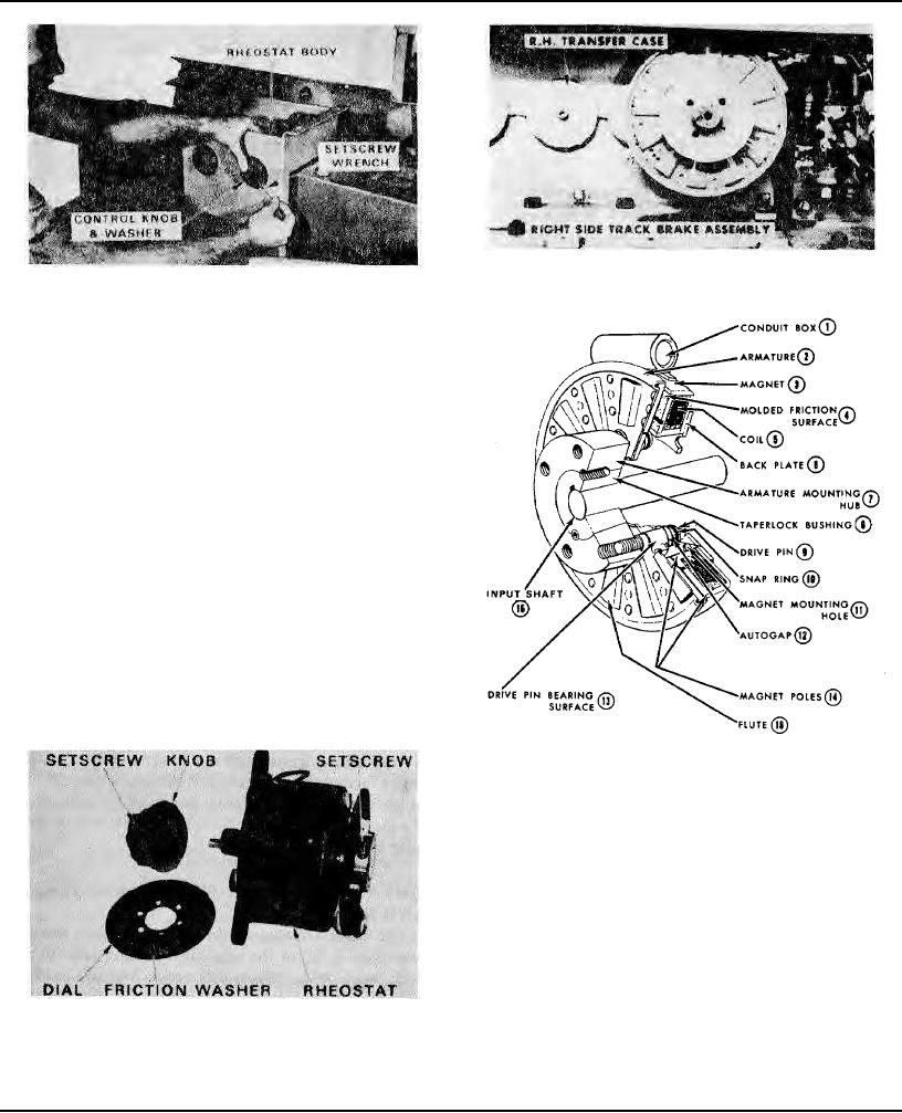
Electric Brake For Right Hand Crawler Track
Tightening Vibrator Control Knob
Figure 40
Figure 38
VIBRATOR CONTROL KNOB
INSTALLATION
The black plastic knob which adjusts the intensity of
vibration for each vibrator, is equipped with a
neporene friction washer to prevent vibration from
rotating the knob during the paving operation.
To correctly assemble a knob to a transformer,
remove walkway cover and loosen the allen
setscrews in knob, and push knob with washer
tightly against dial on control box, while holding
opposite end of shaft. (See Figure 38) Lock Allen
setscrews tightly to the shaft. Rotate knob to check
for sufficient resistance to insure that the knob will
remain in any desired position.
IMPORTANT! If the shaft "bottoms" in control
knob before the required friction is obtained
between washer and dial, it will be necessary to
loosen the setscrews at- the back of the rheostat
inside the housing, and to move the shaft farther
into the rheostat to reduce the amount of shaft in the
knob. Relock setscrews
Cut-away Showing Electric Brake Components
Figure 41
ELECTRICALLY RELEASED BRAKES
The two electrically released brake assemblies are
of the dry friction disc type. Braking force is applied
by permanent magnets in the stationary ring which
attracts the movable disc attached to the gear
reducer shaft. The brake is released when electric
current is passed through a coil surrounding the
permanent magnets to neutralize their magnetic
fields. The movable disc on the shaft is moved away from
the stationary ring by small coil springs and is
then free to revolve. Electric current for brake
Vibrator Rheostat, Dial And Knob
operation is controlled by toggle switch from the
Figure 39
operator's console.
(Continued)
Page 117