
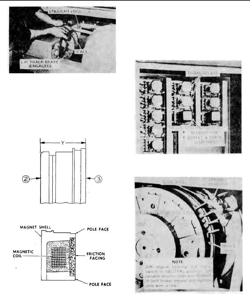
BRAKE ELECTRICAL MODULE
The electrically released brake system includes a
plug-in relay and E.M.F. bleeder module located in
the main electric panel. The relay is for ON-OFF
power application by remote control switch. The
bleeder is for electromotive force dissipation when
the power contacts open. (See Figure 47)
Adjustment of the brake release point is covered
by Figure 48.
Method Of Measuring Wear Of Electric Brake
Figure 44
The simple and accurate wear check is made by
measuring the combined thickness of Magnet (3)
and Armature (2) when the armature is pressed tight
against the magnet. (See Figures 44 & 45) When
both parts are new, dimension Y will be 3-1/16".
When completely worn-out, Y will be 2-3/4". Be
sure that the console switch is at, BRAKE so that the
armature is held tight against the rotor when the
measurement is taken.
Location Of Brake Relays & E.M.F. Bleeder
Figure 47
Side View Brake Showing Wear-check Dimension
Figure 45
Cross-section Thru Electric Brake Magnet Assembly
Figure 46
Variable Resistor For Brake Release Adjustment
Figure 48
Page 119