
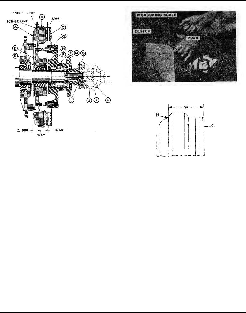
Method Of Measuring Wear Of Electric Clutch
Figure 30
Cross-section Thru Electric Feed Clutch
(Travel clutch identical except for hub)
Figure 29
Side View Of Clutch Showing Wear-check Dimensions
Figure 31
IMPORTANT! Use a machinists dial gauge on
Travel Clutch Adjustment
the face of Rotor "B" to be sure that surface is
running true as it is turned through 360 of rotation.
Refer to Feed Clutch adjustment details in preceding
This will assure 100% contact of the friction face
paragraphs. The travel clutch is identical except for the hub
with the friction face of Armature "C". If the dial
area. Use Figure 29.
gauge indicates more than .010" total variation,
Bushing "E" must be tapped on the side that will
When To Replace Worn Out Armature & Rotor
true-up the Rotor, and the set screws re-tightened to
hold the alignment. If the Rotor is not adjusted in
The clutch armature-rotor set is completely worn-out when
this way and fails to run true, serious clutch slippage
9/32" of the combined friction faces has been worn away.
will result.
When this occurs the two parts must be replaced in order to
CAUTION: DO NOT POUND ON POLES OF
avoid a breakdown at a critical time.
ROTOR.
(5) When clutch is assembled and drive is in
The simple and accurate wear check is made by measuring
place, check .046" opening between Armature "C"
the combined thickness of the Rotor "B" and Armature "C",
Rotor "B". Make adjustment if necessary.
when the movable armature is pressed tight against the rotor.
(6) For other alignment checks, refer to
(See Figures 30 and 31) When both parts are new, dimension
separate clutch manual.
"W" will be 2 1/8". When completely worn-out, "W" will be
NOTE: Care should be taken to keep clutch
1 27/32". Be sure that the armature is held tight against the
clean when assembling.
rotor when the measurement is taken.
Page 113