
TM 5-3895-385-23-2
0309
Manifold Assembly Installation
1. Install two bolts (Figure 2, Item 1), two new lock washers (Figure 2, Item 2), three wires (Figure 2, Item 3),
and manifold assembly (Figure 2, Item 5) onto bracket (Figure 2, Item 4).
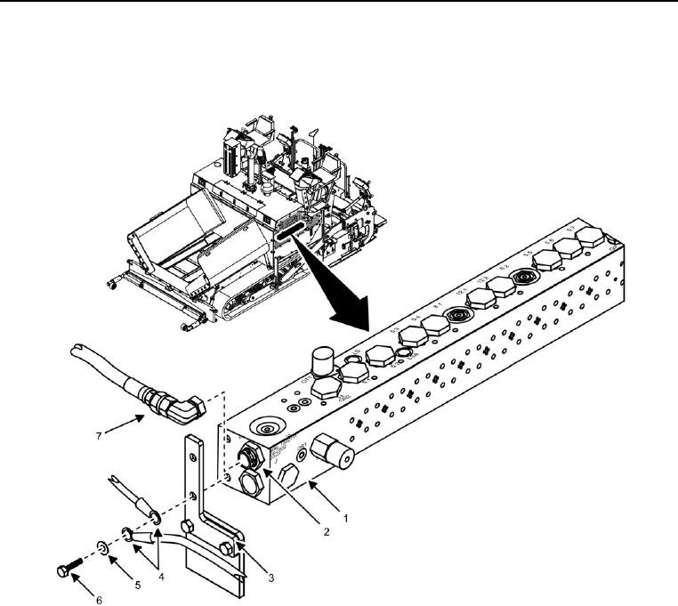
Figure 3. Manifold Assembly Front Side.
2. Install two bolts (Figure 3, Item 6), new lock washers (Figure 3, Item 5), and wires (Figure 3, Item 4) onto
bracket (Figure 3, Item 3) and manifold assembly (Figure 3, Item 1).
NOTE
Additional hose location information can be found in WP 0441.
3. Connect 33 hydraulic hoses (Figure 3, Item 7) onto hydraulic fittings (Figure 3, Item 2).
END OF TASK