
TM 5-3895-385-23-2
0309
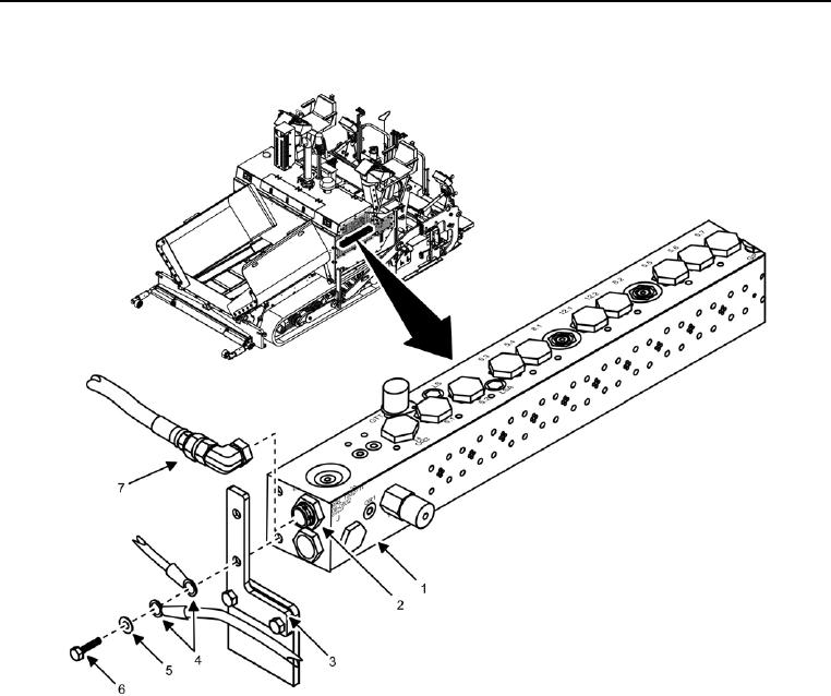
Manifold Assembly Removal
Figure 1. Manifold Assembly Front Side.
CAUTION
Tag and label electrical cables and hydraulic hoses prior to removal. Electrical cables and
hydraulic hoses must be installed correctly for proper operation. Failure to comply may cause
damage to equipment.
NOTE
All hydraulic hoses are removed and installed the same way. One hose shown for clarity.
1. Disconnect 33 hydraulic hoses (Figure 1, Item 7) from hydraulic fittings (Figure 1, Item 2), and cap/plug
hydraulic hoses and hydraulic fittings.
2. Remove two bolts (Figure 1, Item 6), lock washers (Figure 1, Item 5), and wires (Figure 1, Item 4) from
bracket (Figure 1, Item 3) and manifold assembly (Figure 1, Item 1). Discard lock washers.