• Home
  • Download PDF
  • Order CD-ROM
  • Order in Print
Figure 1. Manifold Assembly Front Side.
Figure 3. Manifold Assembly Front Side.

Field Maintenance Manual For Bituminous Material Paving Machine - 2 Page Navigation
  507    508    509    510    511  512  513    514    515    516    517  
img
.
TM 5-3895-385-23-2
0309
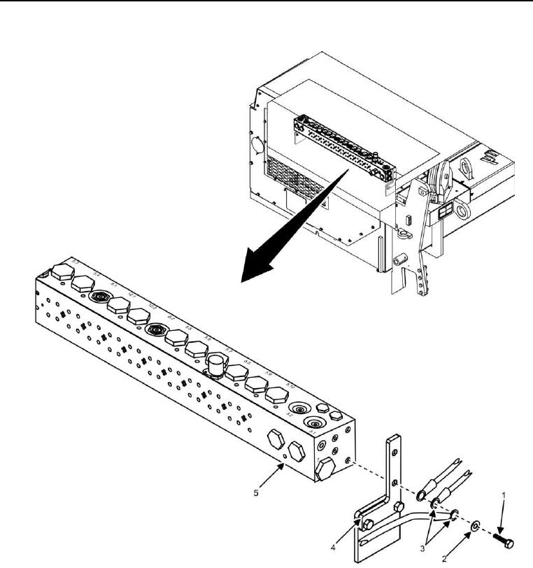
Manifold Assembly Removal -- Continued.
Figure 2. Manifold Assembly Back Side.
3. Remove two bolts (Figure 2, Item 1), two lock washers (Figure 2, Item 2), three wires (Figure 2, Item 3), and
manifold assembly (Figure 2, Item 5) from bracket (Figure 2, Item 4). Discard lock washers.
END OF TASK
0309-3


Privacy Statement
Press Release
Contact

© Copyright Integrated Publishing, Inc.. All Rights Reserved.