
TM 5-3895-385-23-2
0238
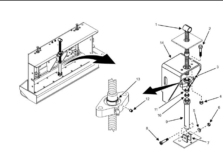
Screed Extension Vertical Attack Angle Adjustment Screw Removal
Figure 1. Screed Extension Vertical Attack Angle Adjustment Screw -- Removal.
1. Remove two bolts (Figure 1, Item 2) and locking nuts (Figure 1, Item 4) from front extension hinge (Figure 1,
Item 14) and flight screw bearing (Figure 1, Item 3). Discard locking nuts.
2. Remove two set screws (Figure 1, Item 12) on locking collar (Figure 1, Item 13).
3. Turn jam nut (Figure 1, Item 10) counterclockwise until it reaches the lower screw housing (Figure 1, Item 9).
4. Turn nut (Figure 1, Item 11) counterclockwise until it reaches the jam nut (Figure 1, Item 10).
5. Slide screed extension vertical attack angle adjustment screw housing (Figure 1, Item 3) to nut (Figure 1, Item
11).