
TM 5-3895-385-23-2
0239
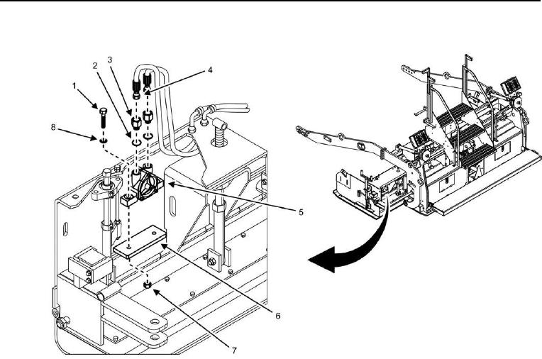
Screed Extension Hydraulic Vibrator Removal
Figure 1. Screed Extension Hydraulic Vibrator -- Removal/Installation.
CAUTION
Tag and label hydraulic hoses prior to removal. Hydraulic hoses must be installed correctly for
proper operation. Failure to comply may cause damage to equipment.
1. Disconnect hydraulic hoses (Figure 1, Item 4) from hydraulic vibrator (Figure 1, Item 5), and cap/plug
hydraulic hoses.
2. Remove two hydraulic fittings (Figure 1, Item 3) and O-rings (Figure 1, Item 2) from hydraulic vibrator (Figure
1, Item 5). Discard O-rings.
3. Remove two bolts (Figure 1, Item 1), lock washers (Figure 1, Item 8), locking nuts (Figure 1, Item 7), and
hydraulic vibrator (Figure 1, Item 5) from hydraulic vibrator bracket (Figure 1, Item 6). Discard lock washers
and locking nuts.
END OF TASK