TM 5-3895-373-34
2.68
REPLACE AUGER BEARING UNITS, SHAFT, AND SPROCKET WHEEL - Continued.
NOTE
This procedure applies to both the
left and right auger shaft assemblies.
Only the right side is shown in this
procedure.
A.
REMOVE.
1.
DISCONNECT SHAFT ASSEMBLY FROM THE
AUGER/CONVEYOR DRIVE CHAIN HOUSING.
WARNING
Use care when removing snap and
retaining rings. Snap and retaining
rings are under spring tension and
can act as projectiles when released
and could cause severe eye injury.
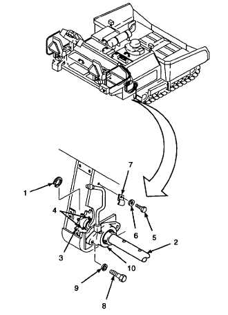
a.
Remove retaining ring (1) from the end of shaft
(2).
NOTE
Rotate shaft (2) and sprocket wheel
(3) to access set screws (4) on the
sprocket wheel, if necessary.
b.
Loosen set screws (4) on sprocket wheel (3).
c.
Remove hex head cap screw (5), washer (6),
and clamp (7) from auger/conveyor drive chain
housing.
d.
Remove
hex
head
cap
screws
(8)
and
lockwashers (9) from bearing unit (10). Discard
lockwashers.
GO TO NEXT PAGE
2-958

