TM 5-3895-373-34
2.64
REPLACE/REPAIR CONVEYOR DRIVE SHAFT, BEARING UNITS, AND SPROCKETWHEELS- Continued.
D.
INSTALL - Continued.
5.
ALIGN DRIVE SHAFT AND SPROCKET
WHEELS.
NOTE
Before setting sprocket wheel width
distance,
ensure
drive
shaft
is
oriented to allow proper adjustment
of sprocket wheel per step 6.
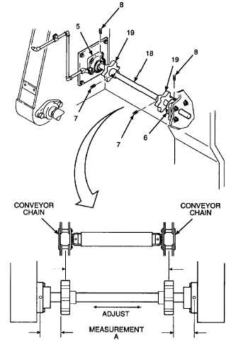
a.
Measure the width of the conveyor chain from
center of the chain links on the left and right
side. Set distance between sprocket wheels
(19) measuring from the center of the sprocket
wheel so it is the same as chain width. Secure
sprocket wheels in place with set screws (7), but
do not tighten at this time. Further adjustments
may have to be made during conveyor chain
assembly installation.
b.
Adjust drive shaft (18) so there is equal distance
between the outside edges of sprocket wheels
(19) and center of lubrication line hole in
bearings, measurement A, on inner and outer
bearing units (5 and 6).
WARNING
Thread locking compound can cause
eye
damage.
Wear
safety
goggles/glasses when using. Avoid
contact with eyes. If compound
contacts eyes, flush eyes with water
and get immediate medical attention.
c.
Remove set screws (8) and apply thread locking
compound to threads.
d.
Install set screws (8) and tighten to 19 lb-ft (26
N.m) using hex head driver socket.
GO TO NEXT PAGE
2-882