TM 5-3895-373-34
C.
INSTALL - Continued.
7.
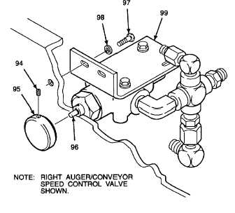
INSTALL AUGER/CONVEYOR SPEED CONTROL
VALVE.
NOTE
Installation procedures for both the left
and right auger/conveyor speed control
valves are the same. The illustrations in
this procedure are for the right speed
control valve. The fittings may be
positioned slightly different for the left
speed control valve.
a.
Install sleeve spacers (98) onto bolts (97).
Thread locking compound can cause
eye
damage.
Wear
safety
goggles/glasses when using. Avoid
contact with eyes. If compound contacts
eyes, flush eyes with water and get
immediate medical attention.
b.
Apply thread locking compound to threads of
bolts (97).
NOTE
Ensure tubes will align with fittings on
valve before tightening bolts.
c.
If installed, remove set screw (94) and knob (95)
from adjustment screw (96) prior to installation.
d.
Position mounting bracket (99) in place and
secure with bolts (97). Tighten bolts to 19 lb-ft
(26 N•m).
e. Position knob (95) on adjustment screw (96) so
that set screw (94) will tighten onto flat on
adjustment screw. Tighten set screw.
GO TO NEXT PAGE
2-779