TM 5-3895-373-34
2.24.
REPLACE/REPAIR TRACK IDLER ROLLER ASSEMBLY- Continued
D.
ASSEMBLE - Continued.
NOTE
The lubrication fitting on the shaft must
be pointing to the outside of the paving
machine. When assembling the RH
track idler roller assembly, install the
shaft with the lubrication fitting up.
When assembling the LH track idler
roller assembly, install the shaft with the
lubrication fitting down.
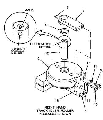
h.
Place shaft (12) with the lubrication fitting up if
assembling the RH track idler roller assembly,
and
with
the
lubrication
fitting
down
if
assembling the LH track idler roller assembly.
i.
Use a marker to indicate location of set screw
(6) locking detents in shaft (12). Mark on the
top end of the shaft.
j.
Apply a thin coating of grease to shaft (12).
k.
Install shaft (12), with mark up, in bore of track
idler roller (9). Fully seat installed shaft in
mating bore of LH track slide (18). Line up the
marks on the shaft with the set screw hole on
the LH track slide.
l.
Press plain seal (13) in RH track slide (7).
Metallic side of plain seal seal must be fully
seated in RH track slide seal bore.
m.
Slide RH track slide (7) down onto shaft (12).
Line up mounting holes in RH track slide with
idler shaft bracket (16).
n.
Install lockwashers (11) onto hex head cap
screws (10).
Thread locking compound can cause
eye damage.
Wear
safety
goggles/glasses
when
using. Avoid contact with eyes. If
compound contacts eyes, flush eyes
with water and get immediate medical
attention.
o. Apply thread locking compound (Item 13,
Appendix B) to threads of hex head cap screws (10).
p.
Install lockwashers (11) and hex head cap
screws (10).
q.
Secure
track
idler
roller
assembly
to
workbench using a C-clamp.
r.
Tighten hex head cap screws (10 and 14) to
355 lb-ft (481 N•m) using socket wrench
adapter (Item 6, Appendix D).
s.
Remove C-clamp and cribbing from track idler
roller assembly.
t.
Apply thread locking compound (Item 14,
Appendix B) to threads of set screws (6).
Install set screws and tighten to 42 lb-ft (57
N.m) using hex head driver socket and socket
wrench adapter (Item 7, Appendix D). Ensure
set screws engage locking detents of shaft
(12).
GO TO NEXT PAGE
2-512


