TM 5-3895-373-34
E.
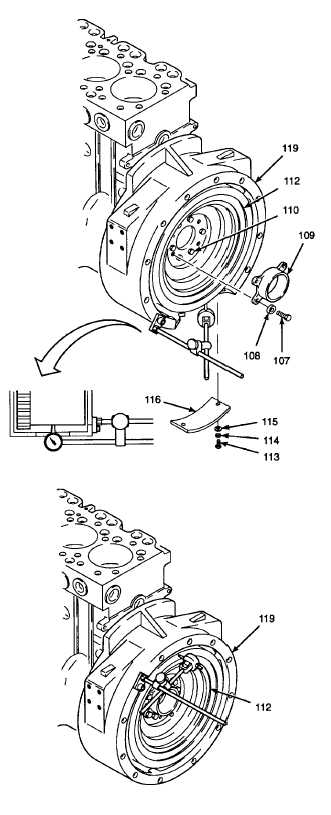
INSTALL - Continued.
e.
Install a dial indicator onto edge of flywheel
housing (119).
f.
With tip of dial indicator against outer diameter
of flywheel (112), turn flywheel and measure
trueing of flywheel.
g.
Flywheel trueing must be within 0.012 in. (0, 30
mm) of total dial indicator reading.
h.
If flywheel is not within 0.012 in. (0, 30 mm) of
total dial indicator reading, loosen hex head cap
screws (110).
i.
Tap flywheel in opposite direction of higher
reading.
j.
Tighten hex head cap screws (110) to 80 Ib-ft
(108 N.m).
k.
Install housing (109) with flat washers (108) and
screws (107). Tighten to 36 lb-ft (48 N.m).
1.
Install pressure plate (116) and secure with flat
washers (115), lockwashers (114), and hex head
cap screws (113). Tighten cap screws to 80 Ib-ft
(108 N.m).
m.
Press flywheel (112) toward engine block to take
up crankshaft assembly end float.
n.
Use dial indicator, attached to edge of flywheel
housing (1 19), to measure outermost point of
machined face runout of flywheel (112), in 1.0 in.
(25, 0 mm) increments.
o.
Flywheel runout must be within 0.001 in. (0, 025
mm) per 1.0 in. (25, 0 mm) of flywheel radius
from crankshaft assembly axis to dial indicator
tip.
p.
If flywheel is out of tolerance, replace flywheel
(112) or crankshaft assembly.
q.
Remove dial indicator.
GO TO NEXT PAGE
2-217