TM 5-3895-373-34
E.
ASSEMBLE - Continued.
16.
ASSEMBLE
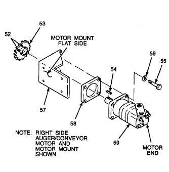
AUGER/CONVEYOR
MOTOR,
SHIM,
DRIVE
SPROCKET
WHEEL,
AND
MOTOR MOUNT.
NOTE
When
assembling
the
left
side
auger/conveyor
motor
the
motor
mount flat side will face the right
when viewed from the motor end with
adapter fitting ports facing up. The
motor mount flat side will face to the
left when assembling the right side
auger/conveyor motor.
a.
Place shim (58) and motor mount (57) onto
auger/conveyor
motor
(59)
mounting
flange. Position the motor mount flat side
to
the
left,
as
shown,
for
right
auger/conveyor motor. Position the motor
mount flat side to the right for left
auger/conveyor motor.
b.
Install washers (56) onto hex head cap
screws (55).
Thread locking compound can cause
eye
damage.
Wear
safety
goggles/glasses when using. Avoid
contact with eyes. If compound
contacts eyes, flush eyes with water
and get immediate medical attention.
c.
Apply thread locking compound to threads
of hex head cap screws (55).
d.
Install and tighten hex head cap screws
(55) to secure auger/conveyor motor (59) to
motor mount (57).
e.
Install key (54) and drive sprocket wheel
(53) onto output shaft of auger/conveyor
motor (59). Snug, up but do not tighten,
sprocket wheel set screws (52).
GO TO NEXT PAGE
2-997


