TM 5-3895-373-34
E.
ASSEMBLE - Continued.
13.
INSTALL
VALVE
HOUSING
AND
COUNTERBALANCE
WEIGHT
ASSEMBLY
ONTO ASSEMBLED VALVE PLATE.
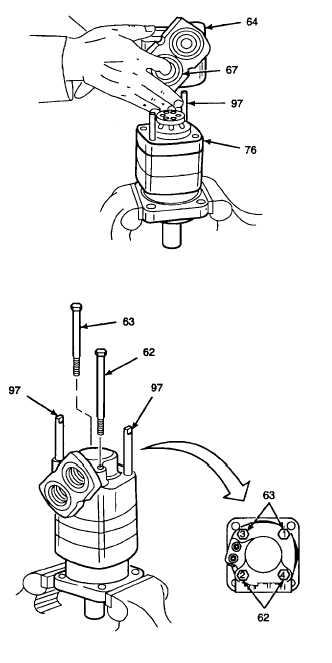
a.
Insert fingers through valve housing (64)
ports
and
hold
counterbalance
weight
assembly (67) in place.
b.
Align case drain port in valve housing (64)
with case drain port of valve plate (76).
NOTE
Ensure
pins
of
counterbalance
weight assembly are engaged into
dowel pin holes of valve housing
during installation.
c.
Install
valve
housing
(64)
with
counterbalance weight assembly (67) over
alignment studs (97) and onto valve plate
(76).
14.
INSTALL
HEX
HEAD
CAP
SCREWS
SECURING AUGER/CONVEYOR HYDRAULIC
MOTOR TOGETHER.
a.
Place one long hex head cap screw (62)
and one short hex head cap screw (63)
through valve housing screw holes and
tighten finger tight.
b.
Remove alignment studs (97).
c.
Place remaining long hex head cap screw
(62) and short hex head cap screw (63) in
place of alignment studs and tighten finger
tight.
d.
Tighten hex head cap screws (62 and 63)
evenly in a crisscross pattern to 750 lb-in
(85 N•m) in sequence as shown.
GO TO NEXT PAGE
2-995


