TM 5-3895-373-20
15.20. ADJUST AND ALIGN MAIN AND EXTENSION SCREED PLATES - Continued.
C.
ALIGN Continued.
Screed
operations
present
a
crushing hazard. Stay clear of screed
during screed operations. Failure to
do so may result in death or serious
injury.
NOTE
Cribbing is used under the screed
only as a safety precaution. Do not
lower the screed onto the cribbing.
Cribbing
may
have
to
be
repositioned
during
alignment
procedure to allow for placement of
straightedge
and
to
view
measurement points.
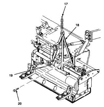
n.
Attach overhead hoist (17) and sling straps (18)
to guide shaft support (19).
o.
Take up slack in sling strap (18) and loosen hex
head cap screws (20).
p.
Place straightedge (10) along trailing edge of
extension screeds at A-A. Raise or lower end of
extension screed to obtain a reading of less than
0.060 in. (1,5 mm). Tighten hex head cap
screws (20).
q.
Lower overhead hoist (17) and remove sling
straps (18).
r.
Repeat steps a through q until proper alignment
is achieved.
s. Connect inboard to outboard extension screed
height adjustment knobs if separated in step d.
(Refer to TM 5-3895-373-10.) t. Start paving
machine engine and position extension screed
halfway per TM 5-3895-373-10.
u.
Shut down paving machine and remove key
from ignition per TM 5-3895-373-10. Position
cribbing under screed.
NOTE: HEX
HEAD
CAP
SCREW
IS
SHOWN
REMOVED FOR CLARITY. DO NOT REMOVE
DURING PROCEDURE.
GO TO NEXT PAGE
15-144