TM 5-3895-373-20
15.20. ADJUST AND ALIGN MAIN AND EXTENSION
B. ADJUST-Continued.
Screed
operations
present
a
crushing hazard. Stay clear of screed
during screed operations. Failure to
do so may result in death or serious
injury.
NOTE
Cribbing is used under the screed
only as a safety precaution. Do not
lower the screed onto the cribbing.
Cribbing
may
have
to
be
repositioned
during
alignment
procedure to allow for placement of
straightedge
and
to
view
measurement points.
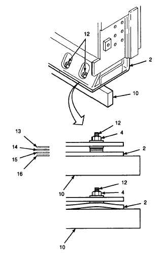
a.
Place straightedge (10) along trailing edge of
screed plate (2) in line with screed plate studs
(12). Have one person support each end of
straightedge.
b.
Measure for gaps between screed plate (2) and
straightedge (10) at each trailing edge stud (12).
NOTE
Shims and plate spacers may be
removed to lower a high point in the
screed
plate.
Follow
the
same
instructions except remove shim(s)
and plate spacer(s) to get screed flat.
c.
If gaps exist, select minimum combination of
shims (13) and plate spacers (14 through 16) to
fill each gap.
Place shims and plate spacers in gaps between
straightedge (10) and screed plate (2) to select
shims and plate spacers.
d.
Loosen self-locking nuts (4) on each stud (12)
that requires shimming and on the studs on
each side of the stud to be shimmed.
e.
Use a hammer and tap a pry bar between
screed plate (2) and screed near stud where
plate spacers are to be added.
f.
Insert selected shim (13) or plate spacer (14, 15,
or 16) between screed plate (2) and screed.
g.
Tap pry bar out of screed. Tighten self-locking
nut (4) to 37 lb-ft (50 N•m).
h.
Place straightedge (10) along trailing edge of
screed plate (2). Measure for gaps between
screed plate and straightedge at each stud (12)
shimmed.
i.
Repeat steps a through h as required to obtain
trailing edge flatness within 0.0625 in. (1,588
mm) for main and extension screed plates.
GO TO NEXT PAGE
15-140