TM 5-3895-373-10
s.
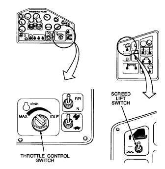
Place screed lift switch to the down, FLOAT
position Lower the screed until the screed rests
on the ground
t.
Shut down paving machine per paragraph 2.11,
step. a through g.
2.26.5. Two Foot Auger and Fender Extension
Installation.
NOTE
Equipment installation instructions
are the same for both the left and
right sides of the paving machine.
Illustrations show installation on the
right side of the paving machine.
To pave widths of 12 to 14 ft (3,7 to 4,3 m), the 2 ft auger
and fender extensions must be installed on both sides of
the paving machine. The 2 ft auger and fender
extension must be compared to determine the left auger
and fender extension from the right auger and fender
extension. Ensure the spiral direction of the auger
extension assemblies match that of the mating auger
shaft. Failure to install the correct auger and fender
extensions on the correct side of the paving machine will
cause the paving material to build up in the auger
chamber and not move the paving material out in front of
the screed
Two persons are required to install the 2 ft auger and
fender extensions.
CAUTION
After installation of the 2 ft auger
extensions, extreme caution must be
taken
not
to
retract
the
screed
extensions
into
the
augers
and
fenders extensions. Damage to the
endgate will result if the endgate is
retracted too far.
To reduce the paving width from between 14 ft (4,3 m)
and 12 ft (3,7 m), carefully retract the extension screed
to obtain the desired paving width.
a.
Start paving machine per paragraph 2.10.
b.
Place throttle control switch to "MAX" position.
c.
Place screed lift switch to the up, RAISE
position. Raise screed fully up.
d.
Fully extend both left and right extension screeds
per paragraph 2.19.
e.
Place wood support blocks under each end of
main screed. Wood supports must be 9 in.
high.
f.
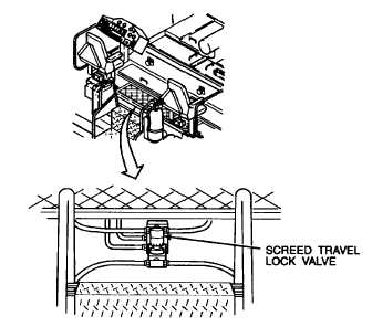
Ensure screed travel lock valve is open.
g.
Place screed lift switch to the down, FLOAT
position. Lower the screed until the screed rests
on the wood blocks.
2-77