TM 5-3895-373-10
(2)
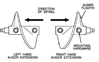
Place the 1 ft auger extensions so that
the mounting hardware for the auger
flights is oriented in the same direction as
the mounting hardware on the mating
auger shaft. If the spiral of the auger
flights does not match that of the mating
auger shaft, then the I ft auger extension
being compared belongs on the opposite
side.
j.
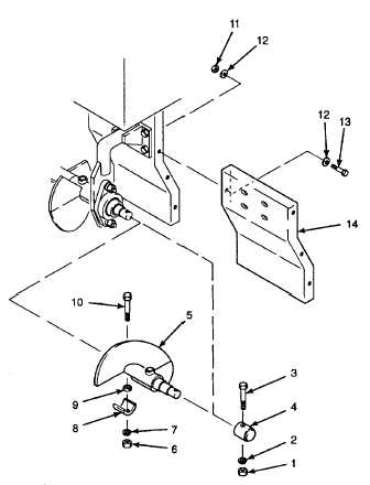
Remove hex nut (1), lockwasher (2), and hex
head cap screw (3) securing shaft cover (4).
Remove shaft cover. These parts will be
reinstalled on end of auger extension shaft.
k.
Locate female end of auger extension assembly
(5) and remove hex nut (6), lockwasher (7), shaft
cover (8), flat washer (9) and hex head cap
screw (10).
NOTE
Auger extensions must be installed
with the same spiral direction as the
mating auger shaft. Failure to install
auger extensions properly will cause
poor distribution of paving material
along the length of the screed and
result in poor paving.
I.
Rotate
auger
extension
so
that
mounting
hardware for the auger flights is oriented in the
same direction as the mounting hardware on the
mating auger shaft. Ensure the spiral direction of
the auger flights match the spiral direction of the
mating auger shaft.
m.
Install female end of auger extension assembly
(5) on the male end of the mating auger shaft
using hex head cap screw (10), flat washer (9),
shaft cover (8), lockwasher (7) and hex nut (6).
n.
Install shaft cover (4) using hex head cap screw
(3), lockwasher (2), and hex nut (1).
o.
Remove hex nuts (11), flat washers (12), and
hex head cap screws (13) from extension fender
(14).
p.
Install extension fender (14) using hex head cap
screws (13), flat washers (12), and hex nuts (l 1).
q.
Start paving machine per paragraph 2.10.
2-74