
Clutch Adjustment (See Figure 49)
(a) Shift 24 Speed Transmission to Neutral. Stop
engine and remove ignition key.
(b) Remove inspection door from Bell Housing
(11). Dis-engage clutch.
(c) Rotate clutch by means of generator V-belt
until Lock Pin (6) is accessible.
(d) Pull out Lock Pin (6) and insert wire or nail to
hold it disengaged.
(e) Hold generator V-belt so that Shaft (15)
cannot turn.
(f) Turn the Yoke and Sleeve Assemblies (2) & (8)
clockwise to reduce slippage when clutch is engaged,
or counterclockwise to increase clearance when
clutch is dis-engaged.
(g) Release Lock Pin (6) to hold the setting, but
be sure the Pin enters one of the locking grooves.
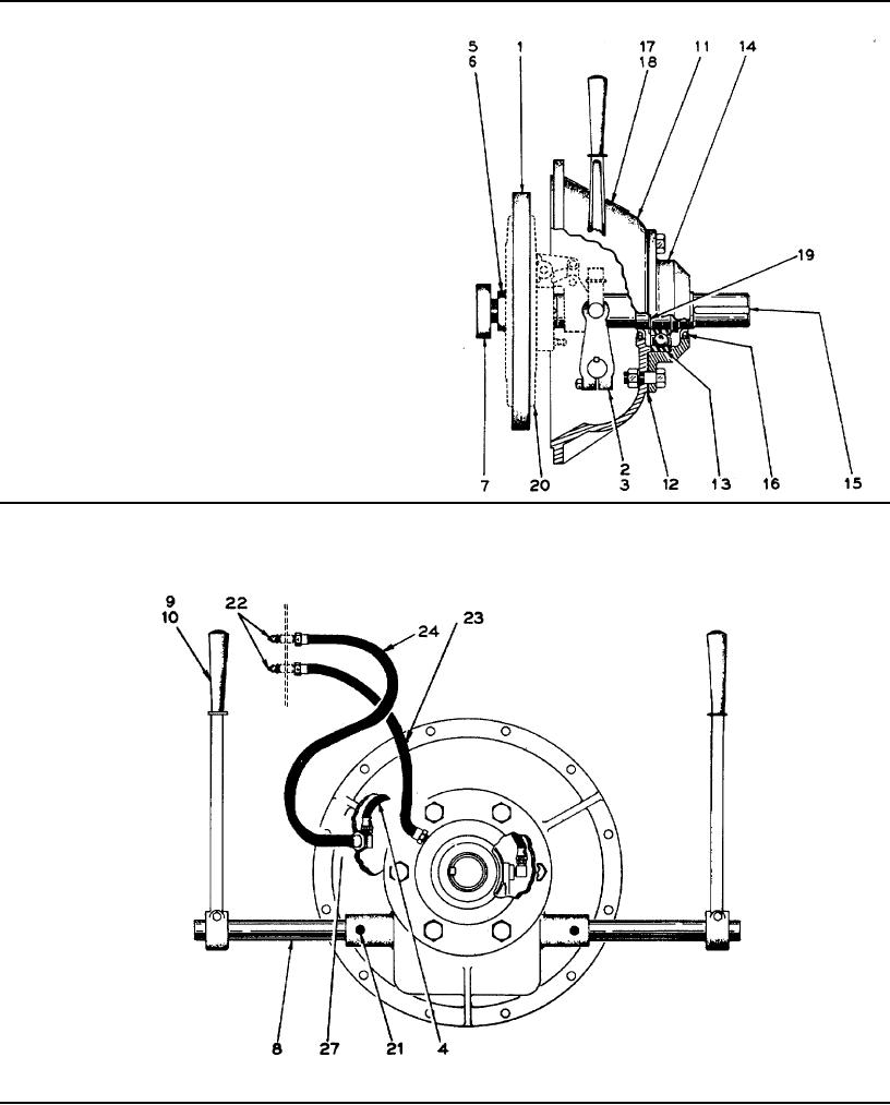
Power Take-off & Clutch Assembly for GM Diesel Engine
Figure 50
Page 121