
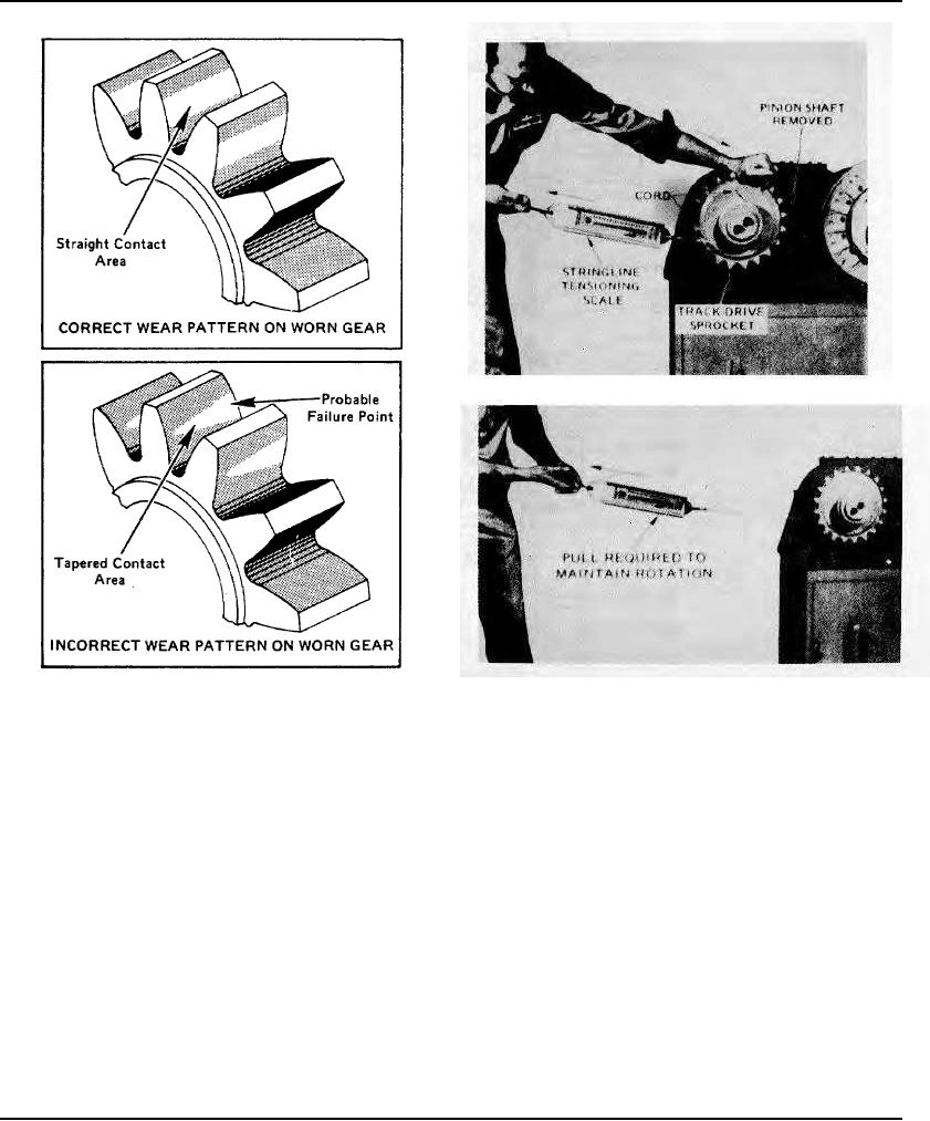
Start Rolling Torque Test Rotation Figure 14
Examples Of Gear Tooth Wear Patterns Figure 13
Reading Rolling Torque Test Scale Figure 15
dimensions.) This should be done with machinists gauges or micrometers. When bores are oversize or out-of-round, a
shock loading occurs during operation and new bearings are quickly ruined. Refer to paragraph J headed "Case Repair"
which follows.
Important! Leave the stub shaft (28) out of the case until after the rolling torque check is made on the output shaft
as described in Step I.
G.- Check the bore of the housing for correct diameter, roundness, and axial alignment at the points where output shaft
bearings (34) and (39) are installed. It is vitally important that these bores be correct as shown in Figures 17 and 18. If
they do not conform to specifications, refer to Step J covering case repair.
H.- Adjust the clearance of the tapered bearings (34) and (39) to produce a .014" pre-load. This is done by adjusting
shim pack (33) so that all end float is just barely eliminated, then removing .014" from shim pack (33) and again
tightening the bearings retainer screws.
NOTE: When normal deflection of the transfer case walls occurs, the pre-load will actually be considerably
less than .014". The rolling torque check described in the following paragraph should be made to verify
that an accurate pre-load has been set.
I.- Make a rolling torque check of the output shaft pre-load in the following manner:
(1) Remove pinion shaft assembly (28) from the case so that output shaft (38) will be free to rotate.
Page 106