
TM 5-3895-385-23-2
0378
Screed Wiring Harness Removal -- Continued.
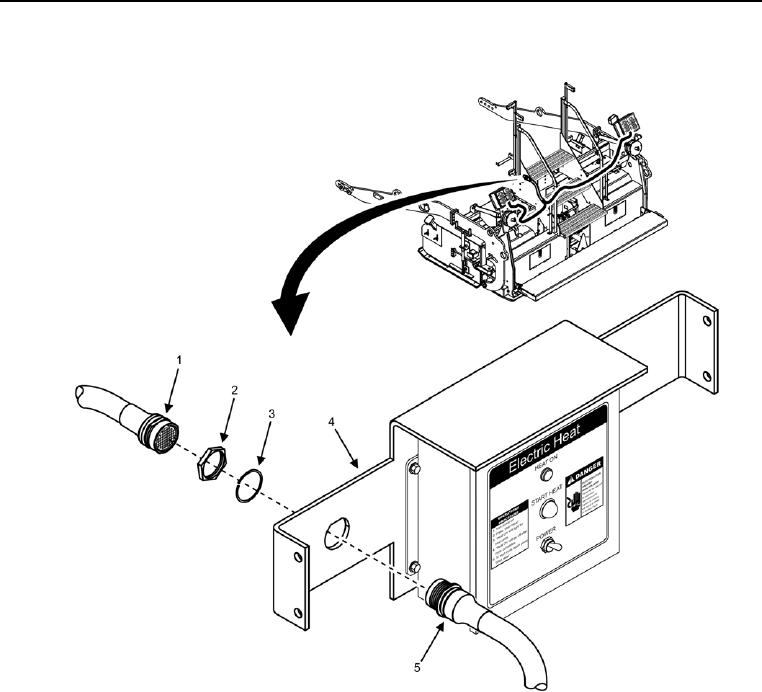
Figure 8. Screed Wiring Harness Bulkhead Connector.
18. Disconnect W6 J2 (Figure 8, Item 5) from W11 J1 (Figure 8, Item 1).
19. Remove nut (Figure 8, Item 2), spacer (Figure 8, Item 3), and W6 J2 (Figure 8, Item 5) from screed electric
heat box bracket (Figure 8, Item 4).
END OF TASK
Screed Wiring Harness Installation
1. Install W6 J2 (Figure 8, Item 5), nut (Figure 8, Item 2), and spacer (Figure 8, Item 3) onto screed electric heat
box bracket (Figure 8, Item 4).
2. Connect W6 J2 (Figure 8, Item 5) onto W11 J1 (Figure 8, Item 1).