• Home
  • Download PDF
  • Order CD-ROM
  • Order in Print
Figure 2. Left Screed Control Box-- Disconnect.
Figure 4. Left Screed Control Wires from Connector -- Removal.

Field Maintenance Manual For Bituminous Material Paving Machine - 2 Page Navigation
  958    959    960    961    962  963  964    965    966    967    968  
img
.
TM 5-3895-385-23-2
0378
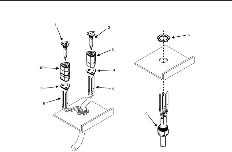
Screed Wiring Harness Removal -- Continued.
Figure 3. Left Screed Control Box Connectors -- Removal.
CAUTION
Tag and label electrical wires prior to removal. Electrical wires must be installed correctly for
proper operation. Failure to comply may cause damage to equipment.
4. Remove wedge cap (Figure 3, Item 1) from W6 J3 (Figure 3, Item 10).
5. Remove wedge cap (Figure 3, Item 2) from W6 J1 (Figure 3, Item 3).
0378-4


Privacy Statement
Press Release
Contact

© Copyright Integrated Publishing, Inc.. All Rights Reserved.