
TM 5-3895-385-23-2
0378
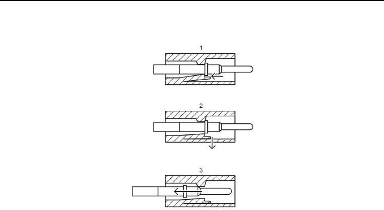
Screed Wiring Harness Removal -- Continued.
Figure 4. Left Screed Control Wires from Connector -- Removal.
6. Insert electrical contact extraction tool into connector (Figure 4, Item 1), and press down on locking tab
(Figure 4, Item 2). Remove six wires (Figure 3, Items 5 and 8) from W6 J3 (Figure 3, Item 10) and W6 J1
(Figure 3, Item 3) while pressing down on locking tab (Figure 4, Item 3).
7. Remove wires (Figure 3, Items 5 and 8) from rear grommets (Figure 3, Items 4 and 9).
8. Remove star nut (Figure 3, Item 6) from housing (Figure 3, Item 7).
9. Remove six wires (Figure 3, Items 5 and 8) from screed control box.