
TM 5-3895-385-23-2
0378
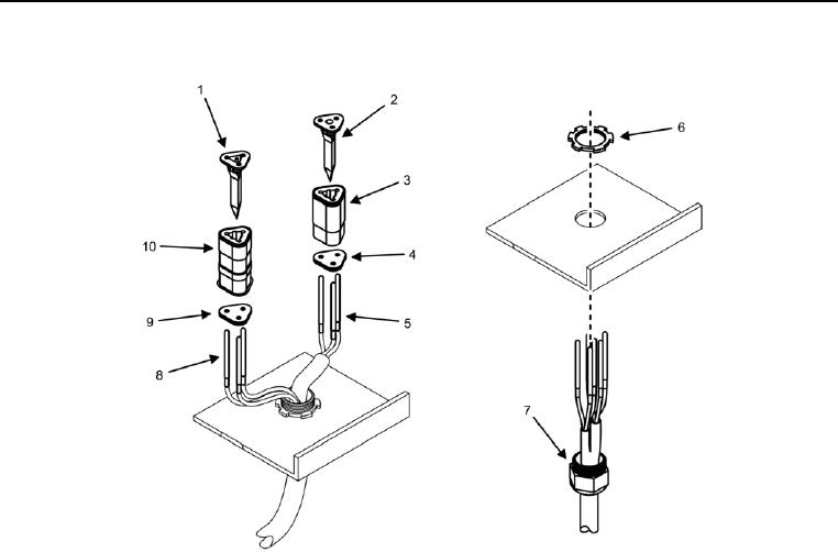
Screed Wiring Harness Installation -- Continued.
Figure 11. Left Screed Control Box Connectors -- Installation.
11. Install six wires (Figure 11, Items 5 and 8) onto screed control box.
12. Install star nut (Figure 11, Item 6) onto housing (Figure 11, Item 7).
13. Install six wires (Figure 11, Items 5 and 8) into rear grommets (Figure 11, Items 4 and 9).
14. Install six wires (Figure 11, Items 5 and 8) into W6 J3 (Figure 11, Item 10) and W6 J1 (Figure 11, Item 3).
15. Install wedge cap (Figure 11, Item 1) onto W6 J3 (Figure 11, Item 10).
16. Install wedge cap (Figure 11, Item 2) onto W6 J1 (Figure 11, Item 3).