
TM 5-3895-385-23-2
0378
Screed Wiring Harness Installation -- Continued.
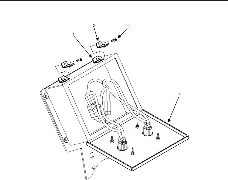
Figure 13. Close Left and Right Screed Control Box.
19. Close left and right screed control box covers (Figure 13, Item 4), and install four screws (Figure 13, Item 3)
and clamps (Figure 13, Item 2) onto mounting brackets (Figure 13, Item 1).
END OF TASK
FOLLOW-ON TASK
1. Install cable ties where necessary.
2. Set BATTERY DISCONNECT switch to ON (TM 5-3895-385-10).
END OF TASK
END OF WORK PACKAGE