
TM 5-3895-385-23-2
0282
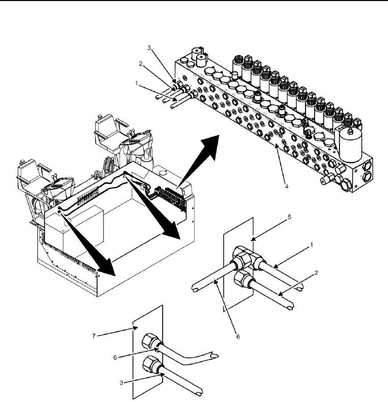
Screed Lift Hydraulic Cylinder Hose Installation -- Continued.
Figure 5. Screed Lift Cylinder Engine Compartment Hydraulic Hoses.
8. Connect hydraulic hose 37 (Figure 5, Item 1), hydraulic hose 40 (Figure 5, Item 2), and hydraulic hose 39
(Figure 5, Item 3) to screed main manifold (Figure 5, Item 4).
9. Connect hydraulic hose 37 (Figure 5, Item 1), hydraulic hose 40 (Figure 5, Item 2), hydraulic hose 39 (Figure
5, Item 3), and hydraulic hose 36 (Figure 5, Item 6) to bulkheads (Figure 5, Items 5 and 7).
END OF TASK