TM 5-3895-385-23-2
0243
Screed Electric Heat Box Disassembly -- Continued.
21. Remove four setscrews (Figure 8, Item 7) and wires (Figure 8, Item 5) from terminal block (Figure 8, Item 3).
22. Remove two screws (Figure 8, Item 1), nuts (Figure 8, Item 14), and terminal block (Figure 8, Item 3) from
screed electric heat box (Figure 8, Item 4).
END OF TASK
Screed Electric Heat Box Assembly
1. Install two screws (Figure 8, Item 1), nuts (Figure 8, Item 14), and terminal block (Figure 8, Item 3) onto
screed electric heat box (Figure 8, Item 2).
2. Install setscrew (Figure 8, Item 11) and wire (Figure 8, Item 12) onto terminal block (Figure 8, Item 3).
3. Install setscrew (Figure 8, Item 6) and wire (Figure 8, Item 4) onto terminal block (Figure 8, Item 3).
4. Install four setscrews (Figure 8, Item 10) and wires (Figure 8, Item 13) onto terminal block (Figure 8, Item 3).
5. Install four setscrews (Figure 8, Item 7) and wires (Figure 8, Item 5) onto terminal block (Figure 8, Item 3).
6.
Install two screws (Figure 8, Item 9) and cover (Figure 8, Item 8) onto terminal block (Figure 8, Item 3).
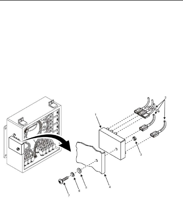
Figure 9. Time Delay Relay -- Installation.
7. Install screw (Figure 9, Item 7), new lock washer (Figure 9, Item 6), flat washer (Figure 9, Item 5), nut (Figure
9, Item 3), and time delay relay (Figure 9, Item 1) onto screed electric heat box (Figure 9, Item 4).
8. Install five wires (Figure 9, Item 2) onto time delay relay (Figure 9, Item 1).

