
TM 5-3895-385-23-2
0233
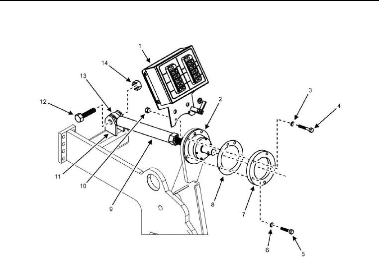
Flight Screw Thread Assembly Installation
Figure 3. Flight Screw Thread Assembly -- Installation.
1. Install flight screw thread assembly (Figure 3, Item 9) to flight screw mounting bracket (Figure 3, Item 2).
2. Install flight screw ball joint (Figure 3, Item 13), bolt (Figure 3, Item 12), and new locking nut (Figure 3, Item
14) into mounting bracket (Figure 3, Item 11).
3. Install flight screw assembly spacer (Figure 3, Item 8) on flight screw assembly, ensuring the key mating
aligns correctly with the assembly.
4. Install outer ring (Figure 3, Item 7) with flight screw assembly, ensuring the key mating aligns correctly with
the assembly.
5. Install three bolts (Figure 3, Item 5) and new lock washers (Figure 3, Item 6) through outer ring (Figure 3, Item
7) and flight screw assembly spacer (Figure 3, Item 8) into flight screw mounting bracket (Figure 3, Item 2).
6. Install two bolts (Figure 3, Item 4), new lock washers (Figure 3, Item 3), nuts (Figure 3, Item 10), and screed
control box assembly (Figure 3, Item 1) onto the back of the flight screw mounting bracket (Figure 3, Item 2).
7. Install flight screw handle assembly (perform steps 1 2 of Flight Screw Handle Assembly Installation task).
END OF TASK