TM 5-3895-373-34
A.
REMOVE - Continued.
3.
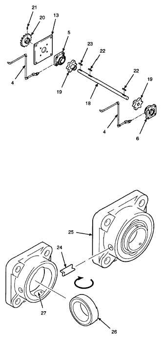
DISASSEMBLE
CONVEYOR
DRIVE
SHAFT
ASSEMBLY.
a.
Remove set screws (21) and sprocket wheel
(20).
b.
Remove bearing plate (13) from drive shaft (18).
c.
Slide inner and outer bearing units (5 and 6) off
of drive shaft (18).
d.
Slide sprocket wheels (19) off of drive shaft (18).
Paving material buildup may interfere with easy
removal of the sprocket wheels; use a sledge
hammer if necessary to tap the sprocket wheels
off of the drive shaft.
e.
Remove keys (22 and 23) from drive shaft (18).
f.
Remove lubrication lines (4) from inner and outer
bearing units (5 and 6).
4.
REMOVE BEARING FROM BEARING HOUSING.
NOTE
Only bearing units difficult to spin need
to be disassembled.
a.
Pull lock pin (24) from bearing housing (25)
using needle nose pliers.
b.
Rotate
bearing
(26)
until
perpendicular
to
bearing housing (25) and in alignment with
housing slots (27).
c.
Pull bearing (26) free of bearing housing (25)
from the front of the bearing unit.
GO TO NEXT PAGE
2-875