TM 5-3895-373-34
2.48
REPAIR AUGER/CONVEYOR SPEED CONTROL VALVE - Continued. ’4
D.
ASSEMBLE Continued.
g.
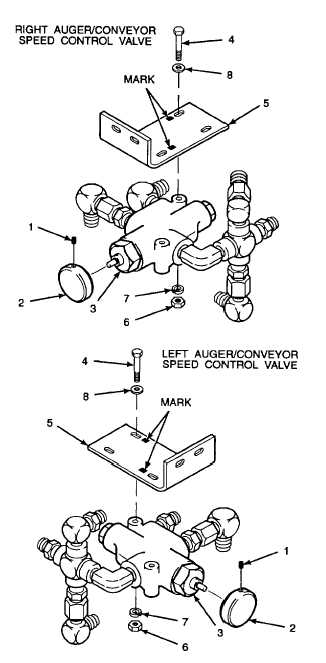
Align mounting bracket (5) onto the top of
auger/conveyor speed control valve (3) using
marks made during disassembly.
h.
Install hex head cap screws (4) and flat washers
(8) through the front and rear holes of mounting
bracket (5) as marked during disassembly and
auger/conveyor speed control valve (3) and line
up the marks on the bracket with the cap screw
heads.
WARNING
Thread locking compound can cause
eye
damage.
Wear
safety
goggles/glasses when using. Avoid
contact with eyes. If compound
contacts eyes, flush eyes with water
and get immediate medical attention.
i.
Apply thread locking compound
(Item
13,
Appendix B) to threads of hex head cap screws
(4).
j.
Install lockwashers (7) and hex nuts (6). Tighten
hex nuts to 9 lb-ft (12 N•m).
k. Install knob (2) onto auger/conveyor speed
control valve (3). Tighten set screw (1) into
knob.
NOTE
FOLLOW-ON-TASK: Install auger/conveyor speed control valve per paragraph 2.55.
END OF TASK
2-662


