TM 5-3895-373-34
E.
ASSEMBLE - Continued.
NOTE
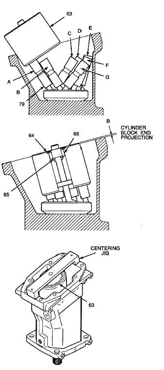
Pistons A and B are inserted to the left while
pistons C and D, E and F, and G are laying to
the right of the mechanical drive housing.
d.
Install cylinder block at an angle, fitting
pistons (79) one at a time into cylinder
block (63) as shown.
e.
After pistons A and B are inserted in
cylinder block (63), insert pistons C and D,
moving the pistons from right to left. Install
pistons E, F, and G while gradually lowering
the cylinder block.
f.
Seat cylinder block (63) down firmly on
pistons (79).
Use care when installing snap and retaining
rings. Snap and retaining rings are under
spring tension and can act as projectiles
when released and could cause severe eye
injury.
NOTE
If shims (65) were removed from cylinder
block (63) at disassembly, install them at this
time.
g.
Use retaining ring pliers and install shims
(65), ring spacer (66), and retaining ring
(64) into cylinder block (63) retaining ring
groove.
h.
Center cylinder block (63) in mechanical
drive housing with a centering jig.
i.
Use a depth gage and measure distance
(B)
cylinder
block
end
projects
from
mechanical drive housing.
j.
Refer to measurement (A) taken in step 2.d
for port plate depth in port plate housing.
k.
Combined cylinder block end projection (B)
and port plate depth (A) must not exceed
0.007 in. (0,02 mm) total.
l.
If cylinder block projection exceeds 0.007
in. (0,02 mm), subtract the difference from
combined measurement. This will give the
required shim thickness as follows:
A - B = total - 0.007 in. (0,02 mm) =
total shim thickness
Total less 0.007 in. (0,02 mm) = shim
thickness required.
GO TO NEXT PAGE
2-457


