TM 5-3895-373-34
E.
ASSEMBLE.
1.
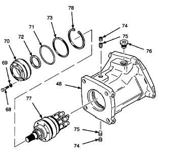
INSTALL SHAFT ASSEMBLY AND MOTOR
COVER INTO MECHANICAL DRIVE HOUSING.
a.
Install shaft assembly (77) into mechanical
drive housing (48). Lightly tap with plastic
hammer if necessary.
Use care when installing snap and
retaining rings. Snap and retaining
rings are under spring tension and
can act as projectiles when released
and could cause severe eye injury.
NOTE
Ensure retaining ring is seated in
retaining ring groove.
b.
Use retaining ring pliers and install retaining
ring
(78).
Ensure
retaining
ring
is
positioned to allow installation of socket
head cap screws (68).
Thread locking compound can cause
eye
damage.
Wear
safety
goggles/glasses when using. Avoid
contact with eyes. If compound
contacts eyes, flush eyes with water
and get immediate medical attention.
NOTE
Shaft assembly (77) must be seated
against retaining ring to allow set
screws to seat in groove of shaft
assembly.
c.
Coat threads of set screws (75 and 74) with
thread
locking
compound
(Item
14,
Appendix B).
d.
Install set screws (75 and 74). Use a hex
head driver socket (Item 89, Appendix D)
and tighten screws to 7 lb-ft (10 N•m).
e.
Install plug (76).
f.
Install shim (73) into mechanical drive
housing (48) against retaining ring (78).
g.
Lubricate o-ring (71) and seal ring (72) with
petrolatum.
h.
Install o-ring (71) into mechanical drive
housing (48) against shim (73).
i.
Use shaft seal installation tool and install
seal ring (72), sealing lip up, into motor
cover (70).
j.
Align screw holes on motor cover (70) with
screw holes on shaft assembly (77).
k.
Press motor cover (70) into mechanical
drive housing (48) by tapping with a plastic
hammer.
I.
Install seal rings (69) onto socket head cap
screws (68).
m.
Install socket head cap screws (68) into
motor cover (70). Use a hex head driver
socket (Item 90, Appendix D) and tighten
cap screws to 7 Ib-ft (10 N•m).
GO TO NEXT PAGE
2-455


