TM 5-3895-373-34
E.
ASSEMBLE Continued.
13.
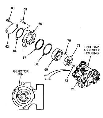
INSTALL GEROTOR SET, A-FLANGE ADAPTER,
AND COVER PLATE ONTO END CAP ASSEMBLY
HOUSING.
a.
Install woodruff key (72) into end cap assembly
housing.
Hydraulic
oil
can
be
moderately
flammable and can be an irritant to the
eyes, skin, and respiratory system.
Avoid
prolonged
exposure.
Eye
protection and rubber gloves must be
worn when working with hydraulic oil.
b.
Lubricate gerotor set (71) with clean hydraulic
oil.
c.
Align and install gerotor set to engage woodruff
key.
d.
Install pin (70) into gerotor cover (69).
Pin and gerotor cover must be aligned
exactly
to
ensure
counterclockwise
operation of charge pump. Improper
alignment of pin and gerotor cover may
result in equipment damage. Align pin
and gerotor cover correctly to prevent
improper rotation of charge pump.
e.
Align pin and gerotor cover so pin is on opposite
side of electronic displacement control (78).
f.
Install pin and gerotor cover into end cap
assembly housing.
g.
Lubricate preformed packing (68) and ring
spacer (67) with petrolatum.
h.
Install preformed packing (68) onto outside
diameter of gerotor cover (69).
i.
Install ring spacer (67) into gerotor cover (69)
groove.
j.
Install hex head cap screws (65) through A-
flange adapter (66)
and
into
end
cap
assembly housing. Tighten screws to 32 Ib-ft
(44 N•m).
k. Rotate pump shaft with slip joint pliers to ensure
charge pump does not bind.
l. Remove hex head cap screws, A-flange adapter,
ring spacer, preformed packing, and gerotor
cover and pin and repeat steps e through I if
pump shaft rotates with no resistance or does
not turn.
m. If removed, install preformed packing (64) into A-
flange adapter.
n. If required, install hex head screws (63) through
cover plate (62) and into A-flange adapter.
Tighten screws to 22 lb-ft (30 N•m).
GO TO NEXT PAGE
2-423


