TM 5-3895-373-34
E.
ASSEMBLE Continued.
10.
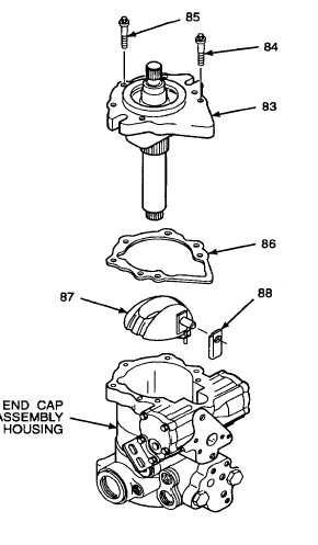
INSTALL SWASH PLATE, GASKET, AND FRONT
COVER.
a.
Turn end cap assembly housing on end to allow
front cover (83) installation while facing up.
Hydraulic oil can be moderately flammable and
can be an irritant to the skin, eyes, and
respiratory system. Avoid prolonged exposure.
Eye protection and rubber gloves must be worn
when working with hydraulic oil.
b.
Lubricate cylinder block assembly with clean
hydraulic oil.
NOTE
Sleeve bearing must be installed to allow
clearance for sleeve bearings on front cover.
c.
Install sleeve bearing (88) onto swash plate (87).
NOTE
When installed, swash plate must rest flush on
cylinder block assembly and sleeve bearing
must engage large center groove on servo
piston.
d.
Install swash plate (87) into end cap assembly
housing.
e.
Install gasket (86) onto end cap assembly
housing.
All parts must be properly aligned before front
cover screws are installed. Do not force front
cover into position if front cover is difficult to
position. Check alignment of internal parts prior
to installing front cover screws. Damage to
swash plate and front cover may occur if front
cover is forced into position.
Ensure sleeve bearings stay in position on front
cover during installation.
f.
Install front cover (83) onto end cap assembly
housing. Align pump shaft splines with cylinder
block splines. Pump shaft may need slight
rotation for spline alignment.
NOTE
When properly aligned, cylinder block
spring holds cover away from end cap
assembly housing a maximum distance
of 0.125 in. (3, 18 mm).
g.
Install screws (84) into front cover. Tighten
screws to 43 lb-ft (58 N.m).
h.
Install screws (85) into front cover. Tighten
screws to 67 lb-ft (91 Nom).
i.
Attach slip joint pliers to pump shaft. Rotate
shaft. Slight resistance should be noted when
turning pump shaft.
j.
If pump shaft does not turn or turns with no
resistance, remove screws from front cover,
remove front cover and swash plate and repeat
steps d through i as necessary.
GO TO NEXT PAGE
2-421


