TM 5-3895-373-34
A.
DISASSEMBLE - Continued.
4.
REMOVE
SLEEVE
BUSHING,
STOP
RING,
BENDIX, AND DRIVE SUPPORT FROM DRIVE SHAFT
AND REMOVE BURRS FROM DRIVE SHAFT.
NOTE
Disassembly
of
assembled
drive
shaft is not required unless it is
necessary to clean, inspect, and
replace one or more parts of the
assembled drive shaft separately.
a.
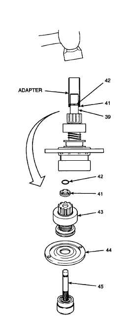
Set assembled drive shaft (39) on work surface
with internal gear end facing down.
b.
Place adapter (Item 2, Appendix D) over sleeve
bushing (41).
c.
Use a plastic hammer and drive sleeve bushing
(41) down toward assembled drive shaft (39) to
break staking and expose stop ring (42).
Use caution when removing stop
ring. Do not use excessive force
when
removing
stop
ring
from
assembled drive shaft. Scratches
and
gouges
may
impair
starter
performance. Pry stop ring gently
from assembled drive shaft.
d.
Gently pry stop ring (42) from assembled drive
shaft (39) with a flat-blade screwdriver. Discard
stop ring. Remove sleeve bushing (41) from
drive shaft.
Do
not
remove
base
metal
on
assembled
drive
shaft
when
removing burrs. Use a fine file to
remove burrs. Excessive removal of
base
metal
may
impair
starter
performance. Work carefully and
remove burrs sparingly.
e.
Use a file to remove any burrs from end of
assembled drive shaft (39), being careful not to
remove base metal during filing.
f.
Slide bendix (43) and drive support (44) from
drive shaft (45).
GO TO NEXT PAGE
2-341


