TM 5-3895-373-34
2.74
REPLACE MAIN SCREED VIBRATOR COMPONENTS - Continued
D.
INSTALL Continued.
4.
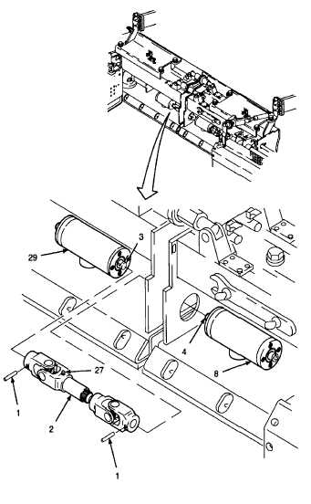
INSTALL UNIVERSAL JOINT ON DRIVE SHAFTS.
NOTE
For proper operation of main screed
vibrators, eccentric weights must be
aligned.
a.
Rotate both drive shafts (3 and 4) by hand to
place eccentric shaft weights in the bottom
position prior to connecting shafts with universal
joint (2). Drive shafts must remain in this
position to ensure proper alignment of eccentric
shaft weights.
Anti-seize compound can cause eye
damage.
Wear
safety
goggles/glasses when using. Avoid
contact with eyes. If compound
contacts eyes, flush eyes with water
and get immediate medical attention.
b.
Apply anti-seize compound to the ends of drive
shafts (3 and 4).
c.
Position universal joint (2) between vibrator
housings (8 and 29).
d.
Install universal joint (2) onto drive shafts (3 and
4). Align pin holes of universal joint and drive
shafts.
e.
Install spring pins (1).
NOTE
FOLLOW-ON-TASKS:
Lubricate universal joint (2) per LO 5-3895-373-12.
Replace main screed vibration motor per TM 5-3895-373-20.
Retract extension screeds per TM 5-3895-373-10.
Install screed steps per TM 5-3895-373-20.
END OF TASK
2-1066


