TM 5-3895-373-34
D.
INSTALL - Continued.
3.
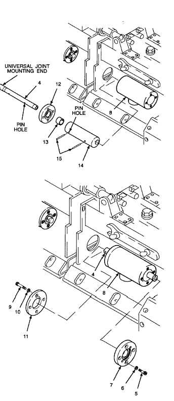
INSTALL BEARING PLATE, RETAINER PLATE,
AND MOTOR MOUNT.
a.
Install bearing plate (12) and spacer (13) onto
drive shaft (4).
b.
Insert drive shaft (4) into eccentric shaft (14).
Rotate drive shaft as required to align pin holes
in drive shaft and eccentric shaft.
c.
Drive spring pins (15) into pin holes of eccentric
shaft (14) and through drive shaft (4). Ensure
pins are flush with, or slightly below, outer
surface of the eccentric shaft.
d.
Install eccentric shaft (14), drive shaft (4), spacer
(13), and bearing plate (12) into vibrator housing
(8).
e.
Install lockwasher (10) on socket head cap
screw (9).
Thread locking compound can cause
eye
damage.
Wear
safety
goggles/glasses when using. Avoid
contact with eyes. If compound
contacts eyes, flush eyes with water
and get immediate medical attention.
f.
Apply thread locking compound to threads of
socket head cap screws (9).
g.
Install retainer plate (11) onto end of drive shaft
(4). Align mounting holes.
h.
Install socket head cap screws (9). Tighten
socket head cap screws to 42 lb-ft (57 N.m)
using a hex head driver socket and socket
wrench adapter.
i.
Install lockwasher (6) onto socket head cap
screws (5).
j.
Apply thread locking compound to threads of
socket head cap screws (5).
k.
Position motor mount (7) over drive shaft (4) in
vibrator housing (8).
l. Install socket head cap screws (5). Tighten
socket head cap screws to 42 lb-ft (57 N.m) using
a hex head driver socket and socket wrench
adapter.
GO TO NEXT PAGE
2-1065


