TM 5-3895-373-34
2.73
REPLACE EXTENSION SCREED GUIDE SHAFT SUPPORT, GUIDE SHAFTS, AND SLEEVE BUSHINGS -
Continued.
D.
INSTALL - Continued.
3.
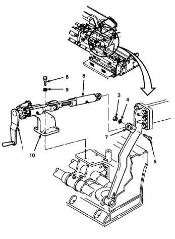
INSTALL THICKNESS CONTROL ASSEMBLY.
a.
Install lockwashers (9) onto hex head cap
screws (8).
Thread locking compound can cause
eye
damage.
Wear
safety
goggles/glasses when using. Avoid
contact with eyes. If compound
contacts eyes, flush eyes with water
and get immediate medical attention.
b.
Apply thread locking compound to threads of hex
head cap screws (8).
c.
Install thickness control assembly (10) and
secure with hex head cap screws (8).
d.
Tighten hex head cap screws (8) to 90 lb-ft (122
N.m).
e.
Turn hand crank (1) to align link (6) with screed
arm bracket (7).
f.
Apply thread locking compound to threads of hex
head cap screw (5).
g.
Install hex head cap screw (5), lockwasher (4),
and hex nut (3). Tighten hex nut to 180 lb-ft
(244 N.m) using socket wrench adapter (Item 6,
Appendix D).
NOTE
FOLLOW-ON-TASKS:
Install extension screed height adjustment controls per
paragraph 2.58 step B.2, steps C.4.a through C.4.c,
steps C.4.g through C.4.k, and steps C.4.p and C.4.q.
Install endgates per TM 5-3895-373-10.
Fully retract extension screed per TM 5-3895-373-10.
Align extension screed per TM 5-3895-373-20.
END OF TASK
2-1056


