TM 5-3895-373-34
C.
INSPECT.
1.
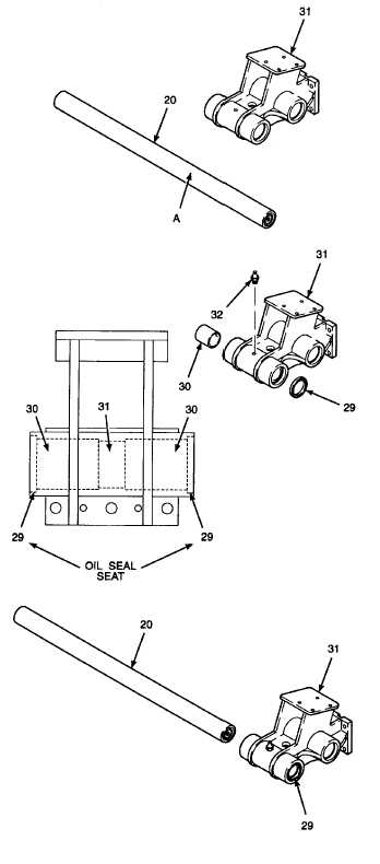
INSPECT GUIDE SHAFT (20) OUTER SURFACE
A FOR CRATCHES, NICKS, CRACKS, OR
DAMAGE THAT WOULD AFFECT THE FULL
EXTENSION OF THE EXTENSION SCREEDS.
POLISH RAISED EDGES OF SMALL NICKS AND
SCRATCHES OUT USING EMERY CLOTH. IF
CRACKS,
WEAR
THROUGH
THE
CHROME
PLATING, EXCESSIVE PIITING, OR OTHER
DAMAGE
IS
FOUND
THAT
CANNOT
BE
REPAIRED BY BEING POLISHED OUT WITHOUT
REMOVING THE CHROME FINISH OF THE
GUIDE SHAFT, REPLACE THE GUIDE SHAFT.
2.
INSPECT GUIDE SHAFT SUPPORT (31) FOR
CRACKS OR DAMAGE THAT WOULD AFFECT
THE OPERATION OF THE GUIDE SHAFT OR
INTERFERE WITH THE FULL EXTENSION OF
THE EXTENSION SCREEDS. REPLACE THE
GUIDE SHAFT SUPPORT IF DAMAGE IS FOUND.
D.
INSTALL.
1.
INSTALL SLEEVE BUSHINGS, PLAIN SEALS
AND
GUIDE
SHAFTS
INTO
GUIDE
SHAFT
SUPPORT ASSEMBLY.
a.
Use a hydraulic press frame and install sleeve
bushings (30) into guide shaft support (31) until
fully seated.
b.
Hone sleeve bushing (30) to 8 microinches.
Ensure that the inside diameter of the sleeve
bushing is between 2.753 and 2.751 in. (69, 926
to 69, 875 mm) using inside calipers.
c.
Press plain seals (29) into the plain seal seats
on both ends of guide shaft support (31) with the
beveled edge facing out.
d.
Install lubrication fittings (32) into guide shaft
support (31).
e.
Apply a light coating of grease to the inner
diameter of plain seals (29) and to guide shaft
(20).
f.
With the help of a second person holding guide
shaft support assembly, slide guide shafts (20)
through plain seals (29) and center the shafts in
the guide shaft support assembly.
GO TO NEXT PAGE
2-1053


